
Datasheet


7
LTC1694-1
16941fa
APPLICATIONS INFORMATION
WUU
U
LTC1694-1
V
CC
GND
V
CC
5V
C1
0.1µF
SMBus1
SMBus2
1
2
5
4
LTC1694-1
V
CC
GND
SMBus1
SMBus2
5
4
1
2
SCL
SDA
DEVICE 1
CLK
IN
CLK
OUT
SMBus
DATA
IN
DATA
OUT
DEVICE N
1694-1 f03
CLK
IN
R
P2
CLK
OUT
DATA
IN
DATA
OUT
R
P1
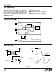
Figure 3. Paralleling Two LTC1694-1 to Provide 4.4mA of Pull-Up Current
Using equations 4 and 5 to check exact value of t
r
:
t
r
= 0.535µs + 0.254µs = 0.79µs
Using equation 7 to check t
f
:
t
f
= 0.222µs
which is less than 0.3µs.
Using equation 1 to check V
OL
:
V
OL
= (3.3 • 700)/[700 + (27 • 10
3
)] = 83mV
which is less than 0.4V.
And using equation 2 to check the initial slew rate:
SR = 3.3/[(27 • 10
3
) • (200 • 10
–12
)] = 0.61V/µs
which is greater than 0.5V/µs.
Therefore, the value of R
P
chosen is 27k.
ACK Data Setup Time
Care must be taken in selecting the value of R
S
(in series
with the pull-down driver) to ensure that the data setup
time requirement for ACK (acknowledge) is fulfilled. An
acknowledge is accomplished by the SMBus host releas-
ing the SDA line (pulling high) at the end of the last bit sent
and the SMBus slave device pulling the SDA line low
before the rising edge of the ACK clock pulse.
The LTC1694-1 2.2mA pull-up current is activated when
the SMBus host releases the SDA line, allowing the
voltage to rise above the LTC1694-1’s comparator thresh-
old of 0.65V. If an SMBus slave device has a high value
of R
S
, a longer time is required for this SMBus slave
device to pull SDA low before the rising edge of the ACK
clock pulse.
To ensure sufficient data setup time for ACK, SMBus slave
devices with high values of R
S
, should pull the SDA low
earlier. Typically, a minimum setup time of 1.5µs is needed
for an SMBus device with an R
S
of 700Ω and a bus
capacitance of 200pF.
An alternative is that the SMBus slave device can hold SCL
line low until the SDA line reaches a stable state. Then, SCL
can be released to generate the ACK clock pulse.
Connecting Multiple LTC1694-1 in Parallel
The LTC1694-1 is designed to guarantee a maximum
SMBus rise time of 1µs with a bus capacitance of 200pF.
In some cases where the bus capacitance is higher than
200pF, multiple LTC1694-1s can be connected in parallel
to provide a higher pull-up current to meet the rise time
requirement. Figure 3 shows a typical application with two
LTC1694-1s connected in parallel to supply a pull-up
current of 4.4mA.
Information furnished by Linear Technology Corporation is believed to be accurate and reliable.
However, no responsibility is assumed for its use. Linear Technology Corporation makes no represen-
tation that the interconnection of its circuits as described herein will not infringe on existing patent rights.