
Datasheet

5
LTC1694
1694fa
SMBus Overview
SMBus communication protocol employs open-drain
drivers with resistive or current source pull-ups. This
protocol allows multiple devices to drive and monitor the
bus without bus contention. The simplicity of resistive or
fixed current source pull-ups is offset by the slow rise
times they afford when bus capacitance is high. Rise
times can be improved by using lower pull-up resistor
values or higher fixed current source values, but the
additional current increases the low state bus voltage,
decreasing noise margins. Slow rise times can seriously
impact data reliability, enforcing a maximum practical
bus speed well below the established SMBus maximum
transmission rate.
Theory of Operation
The LTC1694 overcomes these limitations by using bilevel
hysteretic current sources as pull-ups. During positive
SMBus line transitions, the pull-up current sources typi-
cally provide 2.2mA to quickly slew any parasitic bus
capacitance. Therefore, rise time is dramatically improved,
especially with maximum SMBus loading conditions.
The LTC1694 has separate but identical circuitry for each
SMBus output pin. The circuitry consists of a positive edge
slew rate detector and a voltage comparator.
The LTC1694 nominally sources only 275µA of pull-up
current to maintain good V
OL
noise margin. The 2.2mA
boosted pull-up current is only turned on if the voltage on
the SMBus line voltage is greater than the 0.65V compara-
tor threshold voltage and the positive slew rate of the
SMBus line is greater than the 0.2V/µs threshold of the
slew rate detector. The boosted pull-up current remains on
until the voltage on the SMBus line is within 0.5V of V
CC
and/or the slew rate drops below 0.2V/µs.
Auto Detect Standby Mode
The LTC1694 enters standby mode if the voltage on both
the SCL and SDA lines is high (idle state). In standby mode,
the pull-up currents drop to 100µA, thereby lowering the
system power consumption.
Maximum R
S
Considerations
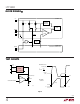
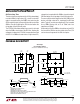
For ESD protection of the SMBus lines, a series resistor R
S
(Figure 2) is sometimes added to the open-drain driver of
the bus agents. This is especially common in SMBus-
controlled smart batteries. The maximum value of R
S
is
limited by the low state noise margin and timing require-
ments of the SMBus specification. The maximum value for
R
S
is 700Ω if resistive pull-ups or fixed value current
sources are used.
In general, an R
S
of 100Ω to 200Ω is sufficient for ESD
protection while meeting both the low state noise margin
and fall time requirement. If a larger value of R
S
is required,
take care to ensure that the low state noise margin and
timing requirement of the SMBus specification is not
violated. Also, the fall time of an SMBus line will also be
increased by using a high value series resistor.
APPLICATIO S I FOR ATIO
WUUU
SDA
R
S
R
ON
1694 F02
DATA
IN
DATA
OUT
Figure 2
Low State Noise Margin
An acceptable V
OL
noise margin is easily achieved with the
low pull-up current (350µA maximum) of the LTC1694.
The maximum value of R
S
is calculated from a desired low
state noise margin (NM
L
):
R
VNM
I
R
S MAX
OL MAX L
PU MAX
ON MAX()
()
()
()
=
−
−
LL-UP
(1)
V
OL(MAX)
: The maximum V
OL
of the SMBus specifica-
tion is 0.4V