
Datasheet

6
LTC1694
1694fa
R
ON(MAX)
: The maximum on resistance of the open-
drain driver
I
PULL-UP(MAX)
: The maximum LTC1694 low pull-up cur-
rent is 350µA
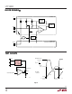
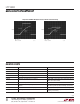
Fall Time
Fall time is a function of the SMBus capacitance, R
S
, R
ON
and the pull-up current. Figure 3 shows the maximum
allowed (R
S
+ R
ON
) based on the Intel SMBus fall time
requirement of 300ns with a 50ns safety margin.
BUS CAPACITANCE (pF)
0
1.4
1.2
1.0
0.8
0.6
0.4
0.2
0
300
1694 F03
100 200 400 500
MAXIMUM VALUE OF R
S
+ R
ON
(kΩ)
V
CC
= 5V
Figure 3. Maximum Value of R
S
+ R
ON
as a Function of Bus
Capacitance for Meeting the SMBus t
f(MAX)
Requirement
The maximum value of R
S
, based on fall time require-
ments, can also be calculated by rearranging equation 6.
Given below are some equations that are useful for calcu-
lating rise and fall time and for selecting the value of R
S
.
Initial Slew Rate
The initial slew rate, SR, of the Bus is determined by:
SR = I
PULL-UP(MIN)
/C
BUS
(2)
C
BUS
is the total capacitance of the SMBus line.
I
PULL-UP(MIN)
is the LTC1694 minimum pull-up current
(125µA).
SR must be greater than SR
THRES
, the LTC1694 slew rate
detector threshold (0.5V/µs max) in order to activate the
2.2mA boosted pull-up current. This limits the maximum
SMBus capacitance.
SMBus Rise Time
Rise time of an SMBus line is derived using equations 3,
4 and 5.
t
r
= t
1
+ t
2
(3)
t
1
= (V
THRES
– V
IL(MAX)
+ 0.15) •
C
BUS
/I
PULL-UP
(4)
if V
IL(MAX)
– 0.15 > V
THRES
, then t
1
= 0µs.
t
2
= (V
IH(MIN)
+ 0.15 – V
THRES
) • C
BUS
/I
PULL-UP(B)
(5)
I
PULL-UP(B)
is the LTC1694 boosted pull-up current (2.2mA
typ).
For an SMBus system, V
IL(MAX)
= 0.8V and V
IH(MIN)
= 2.1V.
For the LTC1694, typically V
THRES
= 0.65V and
I
PULL-UP
= 275µA.
C
BUS
is the total capacitance of the SMBus line.
SMBus Fall Time
Fall time of an SMBus line is derived using equation 6.
t
f
= R
L
• C
BUS
• ln{[(0.9 • V
CC
) – (R
L
• I
PULL-UP(LOW)
)]/
[V
IL(MAX)
– 0.15 – (R
L
• I
PULL-UP(LOW)
)]} (6)
where R
L
is the sum of R
S
and R
ON
(see Figure 2).
Rise and fall time calculation for an I
2
C system is as
follows.
I
2
C Bus Rise and Fall Time
Rise time of an I
2
C line is derived using equation 7.
t
r
= (V
IH(MIN)
– V
IL(MAX)
) • C
BUS
/I
PULL-UP(B)
(7)
Fall time of the I
2
C line can be derived using equation 8.
t
f
= R
L
• C
BUS
• ln{[V
IH(MIN)
– (R
L
• I
PULL-UP
)]/
[V
IL(MAX)
– (R
L
• I
PULL-UP
)]} (8)
For an I
2
C system with fixed input levels, V
IL(MAX)
= 1.5V
and V
IH(MIN)
= 3V.
For an I
2
C system with V
CC
related input levels, V
IL(MAX)
=
0.3 • V
CC
and V
IH(MIN)
= 0.7 • V
CC
.
C
BUS
is the total capacitance of the I
2
C line.
APPLICATIO S I FOR ATIO
WUUU