
Datasheet


14
LTC1755/LTC1756
APPLICATIO S I FOR ATIO
WUUU
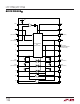
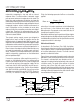
Figure 7. Deactivation Sequence
V
CC
1755 F07
RST
CLK
I/O
AUX2
AUX1
RST = R
IN
DEACTIVATION DIRECTIVE
CLK = C
IN
I/O = DATA
GND
V
IN
V
CC
17556 F08
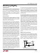
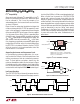
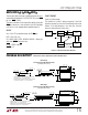
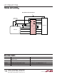
Figure 8. Optimum Bypass Capacitor Placement
Overtemperature Fault Protection
An overtemperature circuit disables the chip and activates
the ALARM pin if the IC’s junction temperature exceeds
150°C.
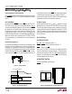
Self-Start Mode
By connecting the CARD pin to the PWR pin, the LTC1755/
LTC1756 can be made to start up automatically when a
Smart Card is detected (Figure 6). In this mode, the READY
pin becomes an interrupt signal indicating to the micro-
controller that a Smart Card is present and that V
CC
, the
charge pump voltage, is at its final value. The Smart Card
remains powered as long as it is detected by the PRES pin.
When the Smart Card is removed the LTC1755/LTC1756
will automatically be deactivated by the fault detection
circuitry.
Deactivation Sequence
For maximum flexibility the Smart Card can be deactivated
either manually or automatically. In manual mode the de-
activation is controlled by explicitly manipulating the
LTC1755/LTC1756 input and control pins (DATA, AUX1IN,
AUX2IN, RIN and CIN followed by PWR and CS). In auto-
matic mode the PWR pin is used to perform the built-in
Figure 6. Self-Start Mode
CARD
TO
MICROCONTROLLER
PWR
READY
1755 F06
deactivation sequence. Once PWR is brought high the built-
in deactivation sequence occurs as shown in Figure 7.
In the event of a fault, the LTC1755/LTC1756 automatically
implement the built-in deactivation sequence.
PC Board Layout
For best performance, the V
IN
and V
CC
capacitors should
be placed as close to the LTC1755/LTC1756 as possible.
This will help reduce ringing due to inductance on the V
IN
and V
CC
pins that could cause problems with the LTC1755/
LTC1756 control circuitry or Smart Card. Figure 8 illus-
trates a possible layout technique using only a single layer
of the PC board.
State Definitions
IDLE/DEACTIVATION
V
CC
, RST, CLK, I/O AUX2, AUX1 = L
READY, ALARM, DATA, AUX2IN, AUX1IN = Z
CARD = PRES ⊕ NC/NO
Once the LTC1755/LTC1756 enter the Idle/Deactivation
state the deactivation sequence begins. The deactivation
sequence will continue until V
CC
is discharged to approxi-
mately 1V. An activation command (PWR = 0V) will only be
acknowledged once this occurs.
ALARM/DEACTIVATION
Same as Idle/Deactivation except:
ALARM = L