
Datasheet
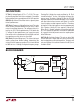


LTC1799
7
1799fc
applicaTions inForMaTion
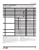
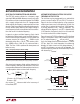
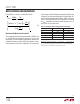
Figure 3. Current Controlled Oscillator
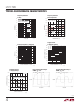
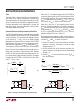
Figure 4. Voltage Controlled Oscillator
ALTERNATIVE METHODS OF SETTING THE OUTPUT
FREQUENCY OF THE LTC1799
The oscillator may be programmed by any method that
sources a current into the SET pin (Pin 3). The circuit in
Figure 3 sets the oscillator frequency using a program-
mable current source and in the expression for f
OSC
, the
resistor R
SET
is replaced by the ratio of 1.13V/I
CONTROL
.
As already explained in the “Theory of Operation,” the
voltage difference between V
+
and SET is approximately
1.13V, therefore, the Figure 3 circuit is less accurate than
if a resistor controls the oscillator frequency.
Figure 4 shows the LTC1799 configured as a VCO. A voltage
source is connected in series with an external 10k resis-
tor. The output frequency, f
OSC
, will vary with V
CONTROL
,
that is the voltage source connected between V
+
and the
SET pin. Again, this circuit decouples the relationship
between the input current and the voltage between V
+
and SET; the frequency accuracy will be degraded. The
oscillator frequency, however, will monotonically increase
with decreasing V
CONTROL
.
SELECTING THE DIVIDER SETTING AND RESISTOR
The LTC1799’s master oscillator has a frequency range
spanning 0.1MHz to 33MHz. However, accuracy may suffer
if the master oscillator is operated at greater than 10MHz
with a supply voltage lower than 4V. A programmable
divider extends the frequency range to greater than three
decades. Table 1 describes the recommended frequencies
for each divider setting. Note that the ranges overlap; at
some frequencies there are two divider/resistor combina-
tions that result in the desired frequency.
In general, any given oscillator frequency (f
OSC
) should
be obtained using the lowest master oscillator frequency.
Lower master oscillator frequencies use less power and
are more accurate. For instance, f
OSC
= 100kHz can be
obtained by either R
SET
= 10k, N = 100, master oscilla-
tor = 10MHz or R
SET
= 100k, N = 10, master oscillator =
1MHz. The R
SET
= 100k is preferred for lower power and
better accuracy.
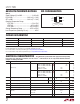
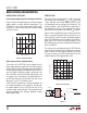
Table 1. Frequency Range vs Divider Setting
DIVIDER SETTING FREQUENCY RANGE
÷1 ⇒ DIV (Pin 4) = GND
>500kHz*
÷10 ⇒ DIV (Pin 4) = Floating
50kHz to 1MHz
÷100 ⇒ DIV (Pin 4) = V
+
<100kHz
*At master oscillator frequencies greater than 10MHz (R
SET
< 10kΩ), the
LTC1799 may suffer reduced accuracy with a supply voltage less than 4V.
After choosing the proper divider setting, determine the
correct frequency-setting resistor. Because of the linear
correspondence between oscillation period and resistance,
a simple equation relates resistance with frequency.
R
SET
=10k •
10MHz
N • f
OSC
, N =
100
10
1
(R
SETMIN
= 3k (5V Supply), 5k (3V Supply),
R
SETMAX
= 1M)
Any resistor, R
SET
, tolerance adds to the inaccuracy of
the oscillator, f
OSC
.
V
+
1
2
3
5
400kHz TO 21MHz
(APPROXIMATE, SEE TEXT)
V
+
0.1µF
I
CONTROL
5µA TO 200µA
1799 F03
4
GND
N = 1
LTC1799
SET
OUT
DIV
10MHz
N
ƒ
OSC
≅
• • I
CONTROL
I
CONTROL
EXPRESSED IN (A)
10kΩ
1.13V
V
+
1
2
3
5
V
+
0.1µF
R
SET
10k
V
CONTROL
0V TO 1.13V
1799 F04
4
GND
N = 1
LTC1799
SET
OUT
DIV
+
–
10MHz
N
ƒ
OSC
≅
• • 1 –
V
CONTROL
1.13V
10k
R
SET
( )