
Datasheet


28
LTC1966
sn1966 1966fas
7. Output is noisy with >10kHz inputs.
– This is a fundamental characteristic of this topol-
ogy. The LTC1966 is designed to work very well
with inputs of 1kHz or less. It works okay as high as
1MHz, but it is limited by aliased ∆Σ noise.
Solution: Bandwidth limit the input or digitally filter
the resulting output.
8. Large errors occur at crest factors approaching, but
less than 4.
– Insufficient averaging.
Solution: Increase C
AVE
. See “Crest Factor and AC +
DC Waveforms” section for discussion of output
droop.
9. Screwy results, errors > spec limits, typically 1% to 5%.
– High impedance (85kΩ) and high accuracy (0.1%)
require clean boards! Flux residue, finger grime, etc.
all wreak havoc at this level.
Solution: Wash the board.
LTC1966
KEEP BOARD CLEAN
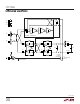
10. Gain is low by ≅1% or more, no other problems.
– Probably due to circuit loading. With a DMM or a
10× scope probe, Z
IN
= 10MΩ. The LTC1966
output is 85kΩ, resulting in –0.85% gain error.
Output impedance is higher with the DC accurate
post filter.
Solution: Remove the shunt loading or buffer the
output.
– Loading can also be caused by cheap averaging
capacitors.
Solution: Use a high quality metal film capacitor
for C
AVE
.
200mV
RMS
IN
–0.85%
DMM
DCV
LTC1966
10M
5
85k
6
V
OUT
OUT RTN
1966 TS10
LOADING DRAGS DOWN GAIN
mV
APPLICATIO S I FOR ATIO
WUUU