
Datasheet


LTC1992 Family
25
1992fb
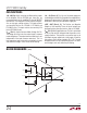
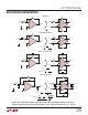
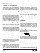
BLOCK DIAGRAMS
(1992-X)
–
–
+
+
+V
S
+V
S
–IN
V
MID
+IN
–V
S
+V
S
–V
S
–V
S
+OUT
–OUT
V
OCM
200k
200k
R
IN
R
FB
R
IN
R
FB
4
5
26
1
3
7
8
1992-X BD
PART
LTC1992-1
LTC1992-2
LTC1992-5
LTC1992-10
R
IN
30k
30k
30k
15k
R
FB
30k
60k
150k
150k
APPLICATIONS INFORMATION
Theory of Operation
The LTC1992 family consists of five fully differential, low
power amplifiers. The LTC1992 is an unconstrained fully
differential amplifier. The LTC1992-1, LTC1992-2, LTC1992-
5 and LTC1992-10 are fixed gain blocks (with gains of
1, 2, 5 and 10 respectively) featuring precision on-chip
resistors for accurate and ultra stable gain.
In many ways, a fully differential amplifier functions much
like the familiar, ubiquitous op amp. However, there are
several key areas where the two differ. Referring to Figure 1,
an op amp has a differential input, a high open-loop gain
and utilizes negative feedback (through resistors) to set
the closed-loop gain and thus control the amplifier’s gain
with great precision. A fully differential amplifier has all of
these features plus an additional input and a complemen-
tary output. The complementary output reacts to the input
signal in the same manner as the other output, but in the
opposite direction. Two outputs changing in an equal but
opposite manner require a common reference point (i.e.,
opposite relative to what?). The additional input, the V
OCM
pin, sets this reference point. The voltage on the V
OCM
input
directly sets the output signal’s common mode voltage and
allows the output signal’s common mode voltage to be
set completely independent of the input signal’s common
mode voltage. Uncoupling the input and output common
mode voltages makes signal level shifting easy.
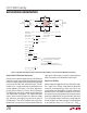
For a better understanding of the operation of a fully dif-
ferential amplifier, refer to Figure 2. Here, the LTC1992
functional block diagram adds external resistors to real-
ize a basic gain block. Note that the LTC1992 functional
block diagram is not an exact replica of the LTC1992
circuitry. However, the Block Diagram is correct and is
a very good tool for understanding the operation of fully
differential amplifier circuits. Basic op amp fundamentals
together with this block diagram provide all of the tools
needed for understanding fully differential amplifier circuit
applications.
The LTC1992 Block Diagram has two op amps, two sum-
ming blocks (pay close attention the signs) and four resis-
tors. Two resistors, R
MID1
and R
MID2
, connect directly to
the V
MID
pin and simply provide a convenient mid-supply
reference. Its use is optional and it is not involved in the
operation of the LTC1992’s amplifier. The LTC1992 functions
through the use of two servo networks each employing