LTC2158-14 Dual 14-Bit 310Msps ADC Description Features n n n n n n n n n n n n The LTC®2158-14 is a 2-channel simultaneous sampling 310Msps 14-bit A/D converter designed for digitizing high frequency, wide dynamic range signals. It is perfect for demanding communications applications with AC performance that includes 68.8dB SNR and 88dB spurious free dynamic range (SFDR). The 1.25GHz input bandwidth allows the ADC to undersample high frequencies with good performance.
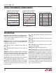
LTC2158-14 Absolute Maximum Ratings Pin Configuration (Notes 1, 2) 64 63 62 61 60 59 58 57 56 55 54 53 52 51 50 49 VDD PAR/SER CS SCK SDI SDO GND DA12_13+ DA12_13– DA10_11+ DA10_11– DA8_9+ DA8_9– DA6_7+ DA6_7 – OVDD TOP VIEW VDD 1 VDD 2 GND 3 AINA+ 4 AINA– 5 GND 6 SENSE 7 VREF 8 GND 9 VCM 10 GND 11 AINB– 12 AINB+ 13 GND 14 VDD 15 VDD 16 48 47 46 45 44 43 42 41 40 39 38 37 36 35 34 33 65 GND OGND DA4_5+ DA4_5– DA2_3+ DA2_3– DA0_1+ DA0_1– CLKOUT+ CLKOUT– DB12_13+ DB12_13– DB10_11+ DB10_11– DB8_9+ DB8
LTC2158-14 Converter Characteristics The l denotes the specifications which apply over the full operating temperature range, otherwise specifications are at TA = 25°C. (Note 5) PARAMETER CONDITIONS MIN Resolution (No Missing Codes) l 14 TYP MAX UNITS Bits Integral Linearity Error Differential Analog Input (Note 6) l –7.5 ±1.2 7.5 LSB Differential Linearity Error Differential Analog Input l –1 ±0.
LTC2158-14 Internal Reference Characteristics The l denotes the specifications which apply over the full operating temperature range, otherwise specifications are at TA = 25°C. (Note 5) PARAMETER CONDITIONS VCM Output Voltage IOUT = 0 MIN TYP MAX 0.435 • VDD – 18mV 0.435 • VDD 0.435 • VDD + 18mV VCM Output Temperature Drift UNITS ±37 VCM Output Resistance –1mA < IOUT < 1mA VREF Output Voltage IOUT = 0 ppm/°C 4 1.225 Ω 1.250 VREF Output Temperature Drift 1.
LTC2158-14 DIGITAL INPUTS AND OUTPUTS The l denotes the specifications which apply over the full operating temperature range, otherwise specifications are at TA = 25°C. (Note 5) SYMBOL PARAMETER DIGITAL DATA OUTPUTS VOD Differential Output Voltage VOS Common Mode Output Voltage RTERM On-Chip Termination Resistance CONDITIONS 100Ω Differential Load, 3.5mA Mode 100Ω Differential Load, 1.75mA Mode 100Ω Differential Load, 3.5mA Mode 100Ω Differential Load, 1.75mA Mode Termination Enabled, OVDD = 1.
LTC2158-14 Typical Performance Characteristics LTC2158-14: Integral Nonlinearity (INL) LTC2158-14: Differential Nonlinearity (DNL) LTC2158-14: 32K Point FFT, fIN = 15MHz, –1dBFS, 310Msps 0.50 2.0 0 1.5 –20 DNL ERROR (LSB) INL ERROR (LSB) 0.5 0 –0.5 AMPLITUDE (dBFS) 0.25 1.0 0 –0.25 –1.0 0 4096 8192 12288 OUTPUT CODE 16383 –0.
LTC2158-14 Typical Performance Characteristics 0 –60 –80 –100 –40 –60 –80 –100 0 20 40 –120 60 80 100 120 140 FREQUENCY (MHz) 0 20 40 100 15000 80 SFDR (dBFS) 20000 5000 8216 215814 G13 20 40 60 LTC2158-14: SNR vs Input Level, fIN = 70MHz, 1.32V Range, 310Msps 50 dBc 0 215814 G14 75 80 70 70 65 SNR (dBFS) 30 30 10 90 40 dBc 40 20 LTC2158-14: SFDR vs Input Frequency, –1dBFS, 1.
LTC2158-14 Typical Performance Characteristics LTC2158-14: IVDD vs Sample Rate, 15MHz Sine Wave Input, –1dBFS LTC2158-14: IOVDD vs Sample Rate, 15MHz Sine Wave Input, –1dBFS LVDS CURRENT 3.5mA –0.5 –1.0 340 INPUT AMPLITUDE (dBFS) 70 320 60 IVDD (mA) IOVDD (mA) LTC2158-14: Frequency Response 360 80 50 LVDS CURRENT 1.75mA 40 300 280 260 50 100 150 200 250 SAMPLE RATE (Msps) 300 215814 G18 240 –2.0 –2.5 –3.0 –3.5 –4.0 30 0 –1.5 0 62 186 124 248 SAMPLE RATE (Msps) 310 215814 G19 –4.
LTC2158-14 Pin Functions SDI (Pin 60): Serial Interface Data Input. In serial programming mode, (PAR/SER = 0V), SDI is the serial interface data input. Data on SDI is clocked into the mode control registers on the rising edge of SCK. In the parallel programming mode (PAR/SER = VDD), SDI selects 3.5mA or 1.75mA LVDS output current (see Table 2). SDI can be driven with 1.8V to 3.3V logic. SCK (Pin 61): Serial Interface Clock Input.
LTC2158-14 Functional Block Diagram VDD OVDD CHANNEL A ANALOG INPUT 14-BIT PIPELINED ADC CORE S/H VCM 0.1µF CORRECTION LOGIC DA12_13 • • • DA0_1 OUTPUT DRIVERS VCM BUFFER DDR LVDS OGND BUFFER GND CLOCK CLOCK/DUTY CYCLE CONTROL CS SCK SDI PAR/SER SPI VREF 2.2µF 1.25V REFERENCE GND RANGE SELECT SENSE ANALOG INPUT BUFFER S/H OVDD 14-BIT PIPELINED ADC CORE CORRECTION LOGIC DB12_13 • • • DB0_1 OUTPUT DRIVERS DDR LVDS CHANNEL B 215814 F01 OGND GND Figure 1.
LTC2158-14 Timing Diagrams Double Data Rate Output Timing, All Outputs Are Differential LVDS N tAP N+3 N+2 N+1 tL tH ENC– ENC+ CLKOUT+ CLKOUT – DA0_1– DA0_1+ DA12_13– DA12_13+ DB0_1– DB0_1+ tC DA0N-5 DA1N-5 DA0N-4 DA1N-4 DA0N-3 DA1N-3 tD DA12N-5 DA13N-5 DA12N-4 DA13N-4 DA12N-3 DA13N-3 DB0N-5 DB1N-5 DB0N-4 DB1N-4 DB0N-3 DB1N-3 DB12_13– DB12_13+ DB12N-5 DB13N-5 DB12N-4 DB13N-4 DB12N-3 DB13N-3 OF– OF+ OF_A N-5 OF_B N-5 OF_A N-4 OF_B N-4 OF_A N-3 OF_B N-3 tSKEW 215814 TD01 215814f 11
LTC2158-14 timing DIAGRAMS SPI Port Timing (Readback Mode) tDS tS tDH tSCK tH CS SCK tDO SDI SDO R/W A6 A5 A4 A3 A2 A1 A0 XX D7 HIGH IMPEDANCE XX D6 XX D5 XX D4 XX D3 XX D2 XX XX D1 D0 SPI Port Timing (Write Mode) CS SCK SDI SDO R/W HIGH IMPEDANCE A6 A5 A4 A3 A2 A1 A0 D7 D6 D5 D4 D3 D2 D1 D0 2158 TD02 215814f 12
LTC2158-14 Applications Information CONVERTER OPERATION INPUT DRIVE CIRCUITS The LTC2158-14 is a two-channel, 14-bit 310Msps A/D converter powered by a single 1.8V supply. The analog inputs must be driven differentially. The encode inputs should be driven differentially for optimal performance. The digital outputs are double data rate LVDS. Additional features can be chosen by programming the mode control registers through a serial SPI port.
LTC2158-14 Applications Information Amplifier Circuits VCM AIN+ AIN– At very high frequencies an RF gain block will often have lower distortion than a differential amplifier. If the gain block is single-ended, then a transformer circuit (Figures 3 and 5) should convert the signal to differential before driving the A/D. The A/D cannot be driven single-ended. LTC2158-14 4.7Ω IN Figure 6 shows the analog input being driven by a high speed differential amplifier.
LTC2158-14 Applications Information Clock Duty Cycle Stabilizer output pair. There are seven LVDS output pairs for channel A (DA0_1+/DA0_1– through DA12_13–/DA12_13+) and seven pairs for channel B (DB0_1+/DB0_1– through DB12_13–/DB12_13+). Overflow (OF+/OF –) and the data output clock (CLKOUT+/CLKOUT–) each have an LVDS output pair. Note that overflow for both channels is multiplexed onto the OF+/OF – output pair. For good performance the encode signal should have a 50% (±5%) duty cycle.
LTC2158-14 Applications Information Programmable LVDS Output Current The default output driver current is 3.5mA. This current can be adjusted by serially programming mode control register A3 (see Table 3). Available current levels are 1.75mA, 2.1mA, 2.5mA, 3mA, 3.5mA, 4mA and 4.5mA. Optional LVDS Driver Internal Termination In most cases, using just an external 100Ω termination resistor will give excellent LVDS signal integrity.
LTC2158-14 Applications Information DATA FORMAT CLKOUT Table 1 shows the relationship between the analog input voltage, the digital data output bits and the overflow bit. By default the output data format is offset binary. The 2’s complement format can be selected by serially programming mode control register A4. OF OF D13 Table 1. Output Codes vs Input Voltage AIN+ – AIN– CLKOUT D13/D0 D12 (1.32V Range) OF D13-D0 (OFFSET BINARY) D13-D0 (2’s COMPLEMENT) >0.
LTC2158-14 Applications Information Alternate Bit Polarity Sleep Mode Another feature that may reduce digital feedback on the circuit board is the alternate bit polarity mode. When this mode is enabled, all of the odd bits (D1, D3, D5, D7, D9, D11, D13) are inverted before the output buffers. The even bits (D0, D2, D4, D6, D8, D10, D12), OF and CLKOUT are not affected.
LTC2158-14 Applications Information Table 2. Parallel Programming Mode Control Bits (PAR/SER = VDD) PIN DESCRIPTION CS Clock Duty Cycle Stabilizer Control Bit 0 = Clock Duty Cycle Stabilizer Off 1 = Clock Duty Cycle Stabilizer On SCK Power Down Control Bit 0 = Normal Operation 1 = Sleep Mode (entire ADC is powered down) SDI LVDS Current Selection Bit 0 = 3.5mA LVDS Current Mode 1 = 1.75mA LVDS Current Mode Serial Programming Mode To use the serial programming mode, PAR/SER should be tied to ground.
LTC2158-14 Applications Information Table 3. Serial Programming Mode Register Map (PAR/SER = GND). X indicates an unused bit that is read back as 0 REGISTER A0: RESET REGISTER (ADDRESS 00h) Write Only D7 D6 D5 D4 D3 D2 D1 D0 RESET X X X X X X X RESET Bit 7 Software Reset Bit 0 = Reset Disabled 1 = Software Reset. All mode control registers are reset to 00h. This bit is automatically set back to zero after the reset is complete.
LTC2158-14 Applications Information REGISTER A3: OUTPUT MODE REGISTER (ADDRESS 03h) D7 X D6 D5 D4 D3 D2 D1 D0 X X ILVDS2 ILVDS1 ILVDS0 TERMON OUTOFF Bits 7-5 Unused Bit Bits 4-2 ILVDS2:ILVDS0 LVDS Output Current Bits 000 = 3.5mA LVDS Output Driver Current 001 = 4.0mA LVDS Output Driver Current 010 = 4.5mA LVDS Output Driver Current 011 = Not Used 100 = 3.0mA LVDS Output Driver Current 101 = 2.5mA LVDS Output Driver Current 110 = 2.1mA LVDS Output Driver Current 111 = 1.
LTC2158-14 Typical Applications Silkscreen Top Top Side 215814f 22
LTC2158-14 TYPICAL APPLICATIONS Inner Layer 2 GND Inner Layer 3 215814f 23
LTC2158-14 TYPICAL APPLICATIONS Inner Layer 4 Inner Layer 5 215814f 24
LTC2158-14 TYPICAL APPLICATIONS Bottom Side 215814f 25
LTC2158-14 TYPICAL APPLICATIONS LTC2158-14 Schematic SPI BUS C13, 0.1µF PAR/SER C7 0.1µF AINA– R33 R8 SENSE C29, 0.1µF C4 2.
LTC2158-14 Package Description Please refer to http://www.linear.com/designtools/packaging/ for the most recent package drawings. UP Package 64-Lead Plastic QFN (9mm × 9mm) (Reference LTC DWG # 05-08-1705 Rev C) 0.70 ±0.05 7.15 ±0.05 7.50 REF 8.10 ±0.05 9.50 ±0.05 (4 SIDES) 7.15 ±0.05 PACKAGE OUTLINE 0.25 ±0.05 0.50 BSC RECOMMENDED SOLDER PAD PITCH AND DIMENSIONS APPLY SOLDER MASK TO AREAS THAT ARE NOT SOLDERED 9 .00 ± 0.10 (4 SIDES) 0.75 ± 0.05 R = 0.10 TYP R = 0.115 TYP 63 64 0.40 ± 0.
LTC2158-14 Typical Application LTC2158-14: 32K Point 2-Tone FFT, fIN = 71MHz and 69MHz, 310Msps VDD OVDD ANALOG INPUT CLOCK S/H 14-BIT PIPELINED ADC CORE S/H DA12_13 • • • DA0_1 OUTPUT DRIVERS DDR LVDS OGND CLOCK/DUTY CYCLE CONTROL ANALOG INPUT CORRECTION LOGIC 0 –40 –60 –80 OVDD CHANNEL B 14-BIT PIPELINED ADC CORE –20 AMPLITUDE (dBFS) CHANNEL A –100 CORRECTION LOGIC DB12_13 • • • DB0_1 OUTPUT DRIVERS DDR LVDS –120 0 20 40 60 80 100 120 140 FREQUENCY (MHz) 215814 TA10b GND 215