LTC2203/LTC2202 16-Bit, 25Msps/10Msps ADCs FEATURES DESCRIPTION n The LTC®2203/LTC2202 are 25Msps/10Msps, sampling 16-bit A/D converters designed for digitizing high frequency, wide dynamic range signals with input frequencies up to 380MHz. The input range of the ADC can be optimized with the PGA front end. n n n n n n n n n n n n Sample Rate: 25Msps/10Msps 81.6dB SNR and 100dB SFDR (2.5V Range) SFDR 90dB at 70MHz (1.667VP-P Input Range) PGA Front End (2.5VP-P or 1.
LTC2203/LTC2202 ABSOLUTE MAXIMUM RATINGS PIN CONFIGURATION OVDD = VDD (Notes 1 and 2) 48 GND 47 PGA 46 RAND 45 MODE 44 OE 43 OF 42 D15 41 D14 40 D13 39 D12 38 OGND 37 OVDD TOP VIEW SENSE 1 VCM 2 VDD 3 VDD 4 GND 5 AIN+ 6 AIN– 7 GND 8 GND 9 CLK 10 GND 11 VDD 12 36 OVDD 35 D11 34 D10 33 D9 32 D8 31 OGND 30 CLKOUT + 29 CLKOUT – 28 D7 27 D6 26 D5 25 OVDD 49 VDD 13 VDD 14 GND 15 SHDN 16 DITH 17 D0 18 D1 19 D2 20 D3 21 D4 22 OGND 23 OVDD 24 Supply Voltage (VDD) .................................. –0.
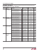
LTC2203/LTC2202 CONVERTER CHARACTERISTICS The l denotes the specifications which apply over the full operating temperature range, otherwise specifications are at TA = 25°C. (Note 4) PARAMETER CONDITIONS MIN Resolution (No missing codes) TYP MAX UNITS 16 Integral Linearity Error Differential Analog Input (Note 5) TA = 25°C ±1.2 ±4.0 LSB Integral Linearity Error Differential Analog Input (Note 5) l ±1.5 ±4.5 LSB Differential Linearity Error Differential Analog Input l ±0.
LTC2203/LTC2202 DYNAMIC ACCURACY The l denotes the specifications which apply over the full operating temperature range, otherwise specifications are at TA = 25°C. AIN = –1dBFS. (Note 4) SYMBOL PARAMETER CONDITIONS SFDR Spurious Free Dynamic Range 2nd or 3rd Harmonic 1MHz Input (2.5V Range, PGA = 0) 1MHz Input (1.667V Range, PGA = 1) 5MHz Input (2.5V Range, PGA = 0) 5MHz Input (2.5V Range, PGA = 0) 5MHz Input (1.
LTC2203/LTC2202 DYNAMIC ACCURACY The l denotes the specifications which apply over the full operating temperature range, otherwise specifications are at TA = 25°C. AIN = –1dBFS. (Note 4) SYMBOL PARAMETER CONDITIONS MIN SFDR Spurious Free Dynamic Range at –25dBFS Dither “ON” 1MHz Input (2.5V Range, PGA = 0) 1MHz Input (1.667V Range, PGA = 1) 5MHz Input (2.5V Range, PGA = 0) 5MHz Input (1.
LTC2203/LTC2202 POWER REQUIREMENTS The l denotes the specifications which apply over the full operating temperature range, otherwise specifications are at TA = 25°C. AIN = –1dBFS. (Note 4) SYMBOL PARAMETER CONDITIONS MIN l 3.135 LTC2203 TYP MAX 3.465 3.135 LTC2202 TYP MAX VDD Analog Supply Voltage Shutdown Power OVDD Output Supply Voltage l IVDD Analog Supply Current l 66 80 42 50 mA PDIS Power Dissipation l 220 264 140 165 mW 2 0.5 3.3 UNITS PSHDN SHDN = VDD , CLK = VDD 3.
LTC2203/LTC2202 TIMING DIAGRAM tAP ANALOG INPUT N+1 N+4 N N+3 N+2 tL tH CLK tD N–7 D0-D15, OF N–6 N–5 N–4 N–3 tC CLKOUT + CLKOUT – 22032 TD01 TYPICAL PERFORMANCE CHARACTERISTICS LTC2203: Differential Nonlinearity (DNL) vs Output Code LTC2203: Integral Nonlinearity (INL) vs Output Code LTC2203: AC Grounded Input Histogram (256k Samples) 1.0 2.0 60000 0.8 1.5 50000 0.6 0.5 0.0 –0.5 –1.0 0.0 –0.2 30000 20000 –0.4 10000 –0.8 16384 32768 49152 –1.
LTC2203/LTC2202 TYPICAL PERFORMANCE CHARACTERISTICS 2 8 4 6 FREQUENCY(MHz) 10 12 0 2 8 4 6 FREQUENCY(MHz) 10 0 –10 –20 –30 –40 –50 –60 –70 –80 –90 –100 –110 –120 –130 –140 0 12 8 4 6 FREQUENCY(MHz) 10 12 0 8 4 6 FREQUENCY(MHz) 140 140 120 120 100 80 60 40 20 10 –50 –40 –30 –20 INPUT LEVEL (dBFS) –10 0 0 –10 –20 –30 –40 –50 –60 –70 –80 –90 –100 –110 –120 –130 –140 12 0 60 40 22032 G13 –50 –40 –30 –20 INPUT LEVEL (dBFS) –10 10 12 22032 GO9 8 4 6 FREQUENCY(MHz) 10 12
LTC2203/LTC2202 TYPICAL PERFORMANCE CHARACTERISTICS 2 8 4 6 FREQUENCY(MHz) 10 12 AMPLITUDE (dBFS) SFDR (dBc AND dBFS) 100 80 60 40 20 –10 SFDR (dBc AND dBFS) 0 0 22032 G19 8 4 6 FREQUENCY(MHz) 10 2 8 4 6 FREQUENCY(MHz) 10 40 0 –70 12 2 8 4 6 FREQUENCY(MHz) 12 22032 G22 –60 22032 G17 10 –50 –40 –30 –20 INPUT LEVEL (dBFS) –10 0 22032 G18 LTC2203: 32K Point FFT, fIN = 30MHz, –10dBFS, PGA = 1 0 –10 –20 –30 –40 –50 –60 –70 –80 –90 –100 –110 –120 –130 –140 0 12 2 22032 G20 140 1
LTC2203/LTC2202 TYPICAL PERFORMANCE CHARACTERISTICS 0 2 8 4 6 FREQUENCY(MHz) 10 0 12 2 8 4 6 FREQUENCY(MHz) 10 0 –10 –20 –30 –40 –50 –60 –70 –80 –90 –100 –110 –120 –130 –140 12 12 0 80 60 40 20 8 4 6 FREQUENCY(MHz) 2 10 0 –70 12 120 105 81 0 –70 79 PGA = 1 95 SNR (dBFS) SFDR (dBc) –10 0 22032 G31 0 22032 G30 PGA = 0 90 PGA = 0 85 78 PGA = 1 77 76 80 –50 –40 –30 –20 INPUT LEVEL (dBFS) –10 80 100 –60 –50 –40 –30 –20 INPUT LEVEL (dBFS) LTC2203: SNR vs Input Frequency
LTC2203/LTC2202 TYPICAL PERFORMANCE CHARACTERISTICS LTC2203: SNR and SFDR vs Sample Rate 110 LTC2203: SNR and SFDR vs Supply Voltage (VDD), fIN = 5MHz 110 RATED MAX SFDR 105 LOWER LIMIT LTC2203: IVDD vs Sample Rate, 5MHz Sine Wave, –1dBFS 75 UPPER LIMIT 105 90 85 IVDD (mA) 95 SFDR 100 SNR SFDR (dBFS) SNR AND SFDR (dBFS) 70 100 95 90 85 SNR 80 SNR 65 60 55 80 75 0 5 75 2.
LTC2203/LTC2202 TYPICAL PERFORMANCE CHARACTERISTICS 2 3 FREQUENCY (MHz) 5 4 0 AMPLITUDE (dBFS) AMPLITUDE (dBFS) 0 –10 –20 –30 –40 –50 –60 –70 –80 –90 –100 –110 –120 –130 –140 1 2 3 FREQUENCY (MHz) 5 4 0 1 22032 G46 120 140 100 120 80 60 40 20 2 3 FREQUENCY (MHz) –50 –40 –30 –20 INPUT LEVEL (dBFS) –10 0 5 4 22032 G49 60 40 –50 –40 –30 –20 INPUT LEVEL (dBFS) –10 5 4 22032 G45 0 1 2 3 FREQUENCY (MHz) 5 4 22032 G48 LTC2202: 32K Point FFT, fIN = 12.
LTC2203/LTC2202 TYPICAL PERFORMANCE CHARACTERISTICS 2 3 FREQUENCY (MHz) 5 4 2 3 FREQUENCY (MHz) 5 4 AMPLITUDE (dBFS) 0 1 22032 G55 140 140 120 120 100 80 60 40 20 –50 –40 –30 –20 INPUT LEVEL (dBFS) –10 0 –70 5 4 2 3 FREQUENCY (MHz) 0 5 4 22032 G58 0 1 40 –10 2 3 FREQUENCY (MHz) 5 4 22032 G57 LTC2202: 32K Point FFT, fIN = 70.
LTC2203/LTC2202 TYPICAL PERFORMANCE CHARACTERISTICS 0 1 2 3 FREQUENCY (MHz) 5 4 0 22032 G61 LTC2202: 32K Point 2-Tone FFT, fIN = 60.2MHz and 70.
LTC2203/LTC2202 TYPICAL PERFORMANCE CHARACTERISTICS LTC2202: SNR and SFDR vs Sample Rate 110 SFDR LOWER LIMIT 50 UPPER LIMIT 49 105 48 SFDR 100 95 90 85 47 IVDD (mA) 100 SNR SFDR (dBFS) SNR AND SFDR (dBFS) 110 RATED MAX 105 LTC2202: IVDD vs Sample Rate, 5MHz Sine Wave, –1dBFS LTC2202: SNR and SFDR vs Supply Voltage (VDD), fIN = 5MHz 95 90 SNR 80 80 75 75 2.8 0 4 8 12 20 16 SAMPLE RATE (Msps) 44 42 41 2.
LTC2203/LTC2202 PIN FUNCTIONS SENSE (Pin 1): Reference Mode Select and External Reference Input. Tie SENSE to VDD with 1k Ω or less to select the internal 2.5V bandgap reference. An external reference of 2.5V or 1.25V may be used; both reference values will set a full scale ADC range of 2.5V (PGA = 0). VCM (Pin 2): 1.25V Output. Optimum voltage for input common mode. Must be bypassed to ground with a minimum of 2.2μF. Ceramic chip capacitors are recommended. VDD (Pins 3, 4, 12, 13, 14): 3.
LTC2203/LTC2202 BLOCK DIAGRAM AIN+ AIN– VDD INPUT S/H FIRST PIPELINED ADC STAGE SECOND PIPELINED ADC STAGE THIRD PIPELINED ADC STAGE FOURTH PIPELINED ADC STAGE FIFTH PIPELINED ADC STAGE GND DITHER SIGNAL GENERATOR CORRECTION LOGIC AND SHIFT REGISTER ADC CLOCKS RANGE SELECT OVDD CLKOUT + CLKOUT – OF SENSE PGA VCM ADC REFERENCE LOW JITTER CLOCK DRIVER CONTROL LOGIC OUTPUT DRIVERS • • • BUFFER VOLTAGE REFERENCE OGND CLK SHDN PGA RAND M0DE DITH D15 D14 D1 D0 22032 F01 OE Figure 1.
LTC2203/LTC2202 APPLICATIONS INFORMATION DYNAMIC PERFORMANCE The signal-to-noise plus distortion ratio [S/(N+D)] is the ratio between the RMS amplitude of the fundamental input frequency and the RMS amplitude of all other frequency components at the ADC output. The output is band limited to frequencies above DC to below half the sampling frequency.
LTC2203/LTC2202 APPLICATIONS INFORMATION CONVERTER OPERATION The LTC2203/LTC2202 are CMOS pipelined multistep converters with a front-end PGA. As shown in Figure 1, the converter has five pipelined ADC stages; a sampled analog input will result in a digitized value seven cycles later (see the Timing Diagram section). The analog input is differential for improved common mode noise immunity and to maximize the input range.
LTC2203/LTC2202 APPLICATIONS INFORMATION the new sample is small, the charging glitch seen at the input will be small. If the input change is large, such as the change seen with input frequencies near Nyquist, then a larger charging glitch will be seen. Common Mode Bias The ADC sample-and-hold circuit requires differential drive to achieve specified performance. Each input may swing ±0.625V for the 2.5V range (PGA = 0) or ±0.417V for the 1.667V range (PGA = 1), around a common mode voltage of 1.25V.
LTC2203/LTC2202 APPLICATIONS INFORMATION Figure 5 demonstrates the use of an LTC1994 differential amplifier to convert a single ended input signal into a differential input signal. The advantage of this method is that it provides low frequency input response; however, the limited gain bandwidth of any op amp will limit the SFDR at high input frequencies. VCM 2.2 μF 499Ω 100pF 523Ω 499Ω – + – 53.
LTC2203/LTC2202 APPLICATIONS INFORMATION PGA Pin The PGA pin selects between two gain settings for the ADC front-end. PGA = 0 selects an input range of 2.5VP-P; PGA = 1 selects an input range of 1.667VP-P. The 2.5V input range has the best SNR; however, the distortion will be higher for input frequencies above 100MHz. For applications with high input frequencies, the low input range will have improved distortion; however, the SNR will be 2.4dB worse. See the Typical Performance Characteristics section.
LTC2203/LTC2202 APPLICATIONS INFORMATION DIGITAL OUTPUTS Data Format Digital Output Buffers The LTC2203/LTC2202 parallel digital output can be selected for offset binary or 2’s complement format. The format is selected with the MODE pin. This pin has a four level logic input, centered at 0, 1/3VDD , 2/3VDD and VDD . An external resistor divider can be user to set the 1/3VDD and 2/3VDD logic levels. Table 1 shows the logic states for the MODE pin.
LTC2203/LTC2202 APPLICATIONS INFORMATION Digital Output Randomizer Interference from the ADC digital outputs is sometimes unavoidable. Interference from the digital outputs may be from capacitive or inductive coupling or coupling through the ground plane. Even a tiny coupling factor can result in discernible unwanted tones in the ADC output spectrum.
LTC2203/LTC2202 APPLICATIONS INFORMATION Output Driver Power Separate output power and ground pins allow the output drivers to be isolated from the analog circuitry. The power supply for the digital output buffers, OVDD , should be tied to the same power supply as for the logic being driven. For example, if the converter is driving a DSP powered by a 1.8V supply, then OVDD should be tied to that same 1.8V supply. In CMOS mode OVDD can be powered with any logic voltage up to 3.6V.
LTC2203/LTC2202 APPLICATIONS INFORMATION Internal Dither Grounding and Bypassing The LTC2203/LTC2202 are 16-bit ADCs with very linear transfer functions; however, at low input levels even slight imperfections in the transfer function will result in unwanted tones. Small errors in the transfer function are usually a result of ADC element mismatches. An optional internal dither mode can be enabled to randomize the input’s location on the ADC transfer curve, resulting in improved SFDR for low signal levels.
R24 OPEN OPEN C6 C4 OPEN LTC2207CUK LTC2206CUK LTC2205CUK LTC2204CUK LTC2203CUK LTC2202CUK DC919A-A DC919A-B DC919A-C DC919A-D DC919A-E DC919A-F ETC1-1T T1 U1 4 5 ASSEMBLY TYPE * VERSION TABLE J2 ANALOG INPUT R32 0 3 2 1 0Ω 0Ω 0.01μF 0.01μF 0.01μF 0.01μF R33 R13 OPEN R12 OPEN R11 OPEN DC < AIN < 70MHz DC < AIN < 70MHz DC < AIN < 70MHz DC < AIN < 70MHz DC < AIN < 70MHz DC < AIN < 70MHz 1 BITS 16 16 16 16 16 16 R8 51Ω C7 8.2pF C3 8.
LTC2203/LTC2202 APPLICATIONS INFORMATION Silkscreen Top Silkscreen Topside 22032fd 28
LTC2203/LTC2202 APPLICATIONS INFORMATION Inner Layer 2 Inner Layer 3 22032fd 29
LTC2203/LTC2202 APPLICATIONS INFORMATION Silkscreen Bottom Side Silkscreen Bottom 22032fd 30
LTC2203/LTC2202 PACKAGE DESCRIPTION UK Package 48-Lead Plastic QFN (7mm × 7mm) (Reference LTC DWG # 05-08-1704) 0.70 ±0.05 5.15 ± 0.05 5.50 REF 6.10 ±0.05 7.50 ±0.05 (4 SIDES) 5.15 ± 0.05 PACKAGE OUTLINE 0.25 ±0.05 0.50 BSC RECOMMENDED SOLDER PAD PITCH AND DIMENSIONS APPLY SOLDER MASK TO AREAS THAT ARE NOT SOLDERED 7.00 ± 0.10 (4 SIDES) 0.75 ± 0.05 R = 0.10 TYP R = 0.115 TYP 47 48 0.40 ± 0.10 PIN 1 TOP MARK (SEE NOTE 6) 1 2 PIN 1 CHAMFER C = 0.35 5.15 ± 0.10 5.50 REF (4-SIDES) 5.15 ± 0.
LTC2203/LTC2202 RELATED PARTS PART NUMBER DESCRIPTION COMMENTS LTC1748 14-Bit, 80Msps ADC 76.3dB SNR, 90dB SFDR, 48-Pin TSSOP Package LTC1750 14-Bit, 80Msps Wideband ADC Up to 500MHz IF Undersampling, 90dB SFDR LT1993-2 High Speed Differential Op Amp 800MHz BW, 70dBc Distortion at 70MHz, 6dB Gain LT1994 Low Noise, Low Distortion Fully Differential Input/Output Amplifier/Driver Low Distortion: –94dBc at 1MHz LTC2204 16-Bit, 40Msps, 3.3V ADC 480mW, 79.