
Datasheet


LTC2377-20
19
237720f
For more information www.linear.com/LTC2377-20
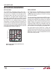
TiMing DiagraMs
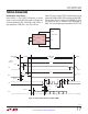
OV
DD
237720 F17a
CONVERT
IRQ
DATA IN
DIGITAL HOST
CLK
CNV
LTC2377-20
BUSY
SDO
B
SCK
RDL/SDI
CNV
LTC2377-20
SDO
A
SCK
RDL/SDI
CHAIN
OV
DD
CHAIN
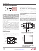
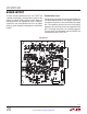
Chain Mode, Multiple Devices
When CHAIN = OV
DD
, the LTC2377-20 operates in chain
mode. In chain mode, SDO is always enabled and RDL/SDI
serves as the serial data input pin (SDI) where daisy-chain
data output from another ADC can be input.
This is useful for applications where hardware constraints
may limit the number of lines needed to interface to a large
number of converters. Figure 17 shows an example with
two daisy-chained devices. The MSB of converter A will
appear at SDO of converter B after 20 SCK cycles. The
MSB of converter A is clocked in at the SDI/RDL pin of
converter B on the rising edge of the first SCK.
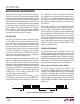
237720 F17
D0
A
D1
A
D18
A
D19
A
D17
B
D18
B
D19
B
SDO
B
SDO
A
= RDL/SDI
B
RDL/SDI
A
= 0
D0
B
D1
B
D17
A
D18
A
D19
A
D0
A
D1
A
1 2 3 18 19 20 21 22 38 39 40
t
DSDOBUSYL
t
SSDISCK
t
HSDISCK
t
BUSYLH
t
CONV
t
HOLD
t
HSDO
t
DSDO
t
SCKL
t
SCKH
t
SCKCH
t
CNVL
t
CYC
CONVERT
CONVERT
SCK
CNV
BUSY
CHAIN = OV
DD
t
QUIET
POWER-DOWNPOWER-DOWN
ACQUIREACQUIRE
Figure 17. Chain Mode Timing Diagram