
Datasheet


LTC2383-16
17
238316f
TIMING DIAGRAM
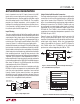
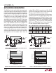
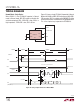
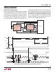
Normal Mode, Multiple Devices
Figure 13 shows multiple LTC2383-16 devices operating
in Normal Mode(CHAIN = 0) sharing CNV, SCK and SDO.
By sharing CNV, SCK and SDO, the number of required
signals to operate multiple ADCs in parallel is reduced.
Since SDO is shared, the RDL/SDI input of each ADC must
be used to allow only one LTC2383-16 to drive SDO at a
time in order to avoid bus conflicts. As shown in Figure 13,
the RDL/SDI inputs idle high and are individually brought
low to read data out of each device between conversions.
When RDL/SDI is brought low, the MSB of the selected
device is output onto SDO. To ensure the MSB is properly
output and captured, SCK must be held low at least 1ns
before and 16ns after bringing RDL/SDI low.
238316 F13
RDL2
RDL1
CONVERT
IRQ
DATA IN
DIGITAL HOST
CLK
CNV
LTC2383-16
SDO
A
SCK
RDL/SDI
CNV
LTC2383-16
SDO
B
SCK
RDL/SDI
CHAIN BUSY
CHAIN
238316 F13
D15
A
SDO
SCK
CNV
BUSY
CHAIN = 0
RDL/SDI
B
RDL/SDI
A
D15
B
D14
B
D1
B
D0
B
D13
B
D14
A
D13
A
D1
A
D0
A
Hi-Z
Hi-ZHi-Z
t
EN
t
HSDO
t
DSDO
t
DIS
t
SCKL
t
SCKH
t
CNVL
123 141516 171819 303132
t
SCK
POWER-UP
CONVERT
POWER-DOWN
CONVERTACQUIRE ACQUIRE
t
HSCKRDL
t
SSCKRDL
t
CONV
t
BUSYLH
Figure 13. Normal Mode With Multiple Devices Sharing CNV, SCK and SDO