
Datasheet


LTC2383-16
18
238316f
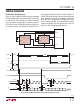
TIMING DIAGRAM
OV
DD
238316 F14a
CONVERT
IRQ
DATA IN
DIGITAL HOST
CLK
CNV
LTC2383-16
BUSY
SDO
B
SCK
RDL/SDI
CNV
LTC2383-16
SDO
A
SCK
RDL/SDI
CHAIN
OV
DD
CHAIN
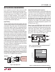
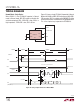
When CHAIN = OV
DD
, the LTC2383-16 operates in Chain
Mode. In Chain Mode, SDO is always enabled and RDL/SDI
serves as the serial data input pin (SDI) where daisychain
data output from another ADC can be input.
This is useful for applications where hardware constraints
may limit the number of lines needed to interface to a large
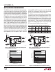
number of converters. Figure 14 shows an example with
two daisy chained devices. The MSB of converter A will
appear at SDO of converter B after 16 SCK cycles. The
MSB of converter A is clocked in at the SDI/RDL pin of
converter B on the rising edge of the first SCK.
238316 F14
D0
A
D1
A
D14
A
D15
A
D13
B
D14
B
D15
B
SDO
B
SDO
A
= RDL/SDI
B
RDL/SDI
A
= 0
D0
B
D1
B
D13
A
D14
A
D15
A
D0
A
D1
A
1 2 3 14 15 161718 3031 32
t
DSDOBUSYL
t
SSDISCK
t
HSDISCK
t
BUSYLH
t
CONV
t
HSDO
t
DSDO
t
SCKL
t
SCKH
t
SCKCH
t
CNVL
t
CYC
CONVERT
CONVERT
ACQUIRE ACQUIRE
POWER-DOWN POWER-UP
SCK
CNV
BUSY
CHAIN = OV
DD
Figure 14. Chain Mode Timing Diagram