
Datasheet


34
LTC2400
TYPICAL APPLICATIONS
U
thermocouple with the highest output is type E, at about
70mV. This circuit does not provide curvature correction
for the Seebeck effect at the cold junction. If the applica-
tion requires very high accuracy, the temperature of the
cold junction should be determined via a separate input
to the A/D, using an RTD for example. The cold junction
compensation can be performed by implementing the
thermocouple’s NBS polynominal curvature correction
in software. (The input to the LTC2400 can be multi-
plexed using the LTC1391 with little degradation.) If a
separate temperature sensor is used to monitor the cold
junction, the connection from the thermocouple to the
LTC2400 can be direct. The junctions formed at the point
where the thermocouple leads meet different metal (e.g.,
copper traces) must be equal in temperature, and the
cold junction sensor must be mounted at that point. Any
temperature differential between the leads, or any differ-
ential between the leads and the temperature sensor will
introduce an error into the reading.
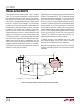
Figure 36 shows an inexpensive circuit with removal of the
DC offset. The output of the LT
®
1077 is attenuated in order
to produce the required coefficient, as well as reduce the
noise and offset error contribution. If used with a ther-
mistor, this circuit can be modified to produce curvature
correction. The removal of the offset associated with diode
forward voltage, or the 273°K overhead on some mono-
lithic temperature sensors, simplifies the use of substan-
tial gain after the thermocouple. Chopper amplifiers such
as the LTC1050 can extend the noise floor of the LTC2400
by as much as a factor of 10 to 20. The use of a gain of 20
in front of the LTC2400 can extend the resolution of a
thermocouple application to 0.02°C or better.
If absolute accuracy is not important, the use of a low
noise bipolar amplifier, such as the LT1028, can extend
the resolution an additional order of magnitude.
Note that achieving high accuracy in the circuit in Figure 36
requires a calibration sequence for circuit offset and gain
correction.
V
IN
SDO
SCK
CS
36.1µV/°C
R5
1k
6
3
R
1mV/°C
2
7
4
5V
+–
2
1
R2
174k*
V
+
V
–
4
*RECOMMENDED 0.1%, ±5ppm IRC AFD SERIES CHIP RESISTORS
5
6
7
5V
10k
60Hz
SELECT R3 FOR
THERMOCOUPLE TYPE
S: 6.19Ω
K: 39.2Ω
J: 49.9Ω
E: 61.9Ω
50Hz
8
V
REF
V
CC
0.1µF
5V
GND
LTC2400
F
O
2400 F35
R3
1k*
R6
6.19Ω
R1
226Ω*
R4
10k*
–
+
LT1077
LM334
SO-8
Figure 36. Inexpensive Amplifier Improves Cold Junction Compensation