
Datasheet

LTC2430/LTC2431
36
24301f
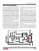
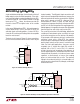
The circuit shown in Figure 42 shows a more rigorous
example of Figure 41, with increased noise suppression
and more protection for remote applications.
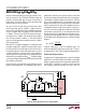
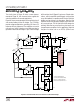
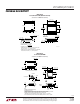
Figure 43 shows an example of gain in the excitation circuit
and remote feedback from the bridge. The LTC1043s
provide voltage multiplication, providing ±10V from a 5V
reference with only 1ppm error. The amplifiers are used at
unity-gain and, hence, introduce a very little error due to
gain error or due to offset voltages. A 1µV/°C offset voltage
APPLICATIO S I FOR ATIO
WUUU
drift translates into 0.05ppm/°C gain error. Simpler alter-
natives, with the amplifiers providing gain using resistor
arrays for feedback, can produce results that are similar to
bridge sensing schemes via attenuators. Note that the
amplifiers must have high open-loop gain or gain error will
be a source of error. The fact that input offset voltage has
relatively little effect on overall error may lead one to use
low performance amplifiers for this application. Note that
the gain of a device such as an LF156, (25V/mV over
350Ω
BRIDGE
0.1µF
1µF
15V15V
–15V
38
14
7
4
13
12
11
10V 5V
15V
U1
LTC1043
6
2
7
4
7
4
–
+
REF
+
REF
–
IN
+
IN
–
GND
V
CC
2431 F43
5V
47µF 0.1µF
10V
+
17
5
15
6
18
3
2
U2
LTC1043
1µF
FILM
8
14
7
4
13
12
11
*
*
*
5V
U2
LTC1043
17
–10V
–10V
LT1236-5
1k
33Ω
Q1
2N3904
0.1µF
15V
–15V
–15V
3
6
2
–
+
1k
33Ω
–10V
10V
Q2
2N3906
*FLYING CAPACITORS ARE
1µF FILM (MKP OR EQUIVALENT)
SEE LTC1043 DATA SHEET FOR
DETAILS ON UNUSED HALF OF U1
LTC1150
LTC1150
20Ω
200Ω
20Ω
200Ω
0.1µF
10µF
+
LTC2430/
LTC2431
Figure 43. LTC1043 Provides Precise 4× Reference for Excitation Voltages