
Datasheet


LTC2600/LTC2610/LTC2620
5
2600fe
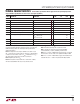
Note 1: Stresses beyond those listed under Absolute Maximum Ratings
may cause permanent damage to the device. Exposure to any Absolute
Maximum Rating condition for extended periods may affect device
reliability and lifetime.
Note 2: Linearity and monotonicity are defi ned from code kL to code
2N – 1, where N is the resolution and k
L
is given by k
L
= 0.016(2
N
/V
REF
),
rounded to the nearest whole code. For V
REF
= 4.096V and N = 16, k
L
=
256 and linearity is defi ned from code 256 to code 65,535.
Note 3: Digital inputs at 0V or V
CC
.
Note 4: DC crosstalk is measured with V
CC
= 5V and V
REF
= 4.096V,
with the measured DAC at mid-scale, unless otherwise noted.
Note 5: R
L
= 2kΩ to GND or V
CC
.
Note 6: Guaranteed by design and not production tested.
Note 7: Inferred from measurement at code 256 (LTC2600),
code 64 (LTC2610) or code 16 (LTC2620), and at full-scale.
Note 8: V
CC
= 5V, V
REF
= 4.096V. DAC is stepped 1/4-scale to 3/4-scale
and 3/4-scale to 1/4-scale. Load is 2k in parallel with 200pF to GND.
Note 9: V
CC
= 5V, V
REF
= 4.096V. DAC is stepped ±1LSB between half-
scale and half-scale – 1. Load is 2k in parallel with 200pF to GND.
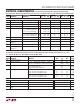
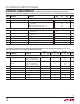
TIMING CHARACTERISTICS
The l denotes specifi cations which apply over the full operating temperature
range, otherwise specifi cations are at T
A
= 25°C. (See Figure 1) (Note 6)
SYMBOL PARAMETER CONDITIONS
LTC2600/LTC2610/LTC2620
UNITSMIN TYP MAX
V
CC
= 2.5V to 5.5V
t
1
SDI Valid to SCK Setup
l
4ns
t
2
SDI Valid to SCK Hold
l
4ns
t
3
SCK High Time
l
9ns
t
4
SCK Low Time
l
9ns
t
5
CS/LD Pulse Width
l
10 ns
t
6
LSB SCK High to CS/LD High
l
7ns
t
7
CS/LD Low to SCK High
l
7ns
t
8
SDO Propagation Delay from SCK Falling Edge C
LOAD
= 10pF
V
CC
= 4.5V to 5.5V
V
CC
= 2.5V to 5.5V
l
l
20
45
ns
ns
t
9
CLR Pulse Width
l
20 ns
t
10
CS/LD High to SCK Positive Edge
l
7ns
SCK Frequency 50% Duty Cycle
l
50 MHz