
Datasheet

LTC2637
22
2637fb
OPERATION
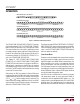
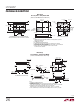
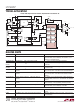
Figure 3. Command and Data Input Format
C3
1ST DATA BYTE
Input Word (LTC2637-12)
Write Word Protocol for LTC2637
C2
C1
C0
A3
A2
A1
A1
D9D10D11
S
W ACK
SLAVE ADDRESS
1ST DATA BYTE
D8
D7 D6 D5 D4
D3
D2
D1 D0 X X X
X
ACK 2ND DATA BYTE ACK 3RD DATA BYTE ACK P
2637 F03
2ND DATA BYTE
INPUT WORD
3RD DATA BYTE
C3
1ST DATA BYTE
Input Word (LTC2637-10)
C2
C1
C0
A3
A2
A1
A0
D7D8D9
D6
D5 D4 D3 D2
D1
D0
XXXXX
X
2ND DATA BYTE 3RD DATA BYTE
C3
1ST DATA BYTE
Input Word (LTC2637-8)
C2
C1
C0
A3
A2
A1
A0
D5D6D7
D4
D3 D2 D1 D0
X
X
XXXXX
X
2ND DATA BYTE 3RD DATA BYTE
The LTC2637-LMI/ LTC2637-LMX/ LTC2637-LZ provides
a full-scale output of 2.5V. The LTC2637-HMI/ LTC2637-
HMX/ LTC2637-HZ provides a full-scale output of 4.096V.
The internal reference can be useful in applications where
the supply voltage is poorly regulated. Internal Reference
mode can be selected by using command 0110b, and is
the power-on default for LTC2637-HZ/ LTC2637-LZ, as
well as for LTC2637-HMI/ LTC2637-LMI.
The 10ppm/°C, 1.25V (LTC2637-LMI/ LTC2637-LMX/
LTC2637-LZ) or 2.048V (LTC2637-HMI/ LTC2637-HMX/
LTC2637-HZ) internal reference is available at the REF pin.
Adding bypass capacitance to the REF pin will improve
noise performance; and up to 10µF can be driven without
oscillation. The REF output must be buffered when driving
an external DC load current.
Alternatively, the DAC can operate in External Reference
mode using command 0111b. In this mode, an input voltage
supplied externally to the REF pin provides the reference
(1V ≤ V
REF
≤ V
CC
) and the supply current is reduced. The
external reference voltage supplied sets the full-scale DAC
output voltage. External Reference mode is the power-on
default for LTC2637-HMX/ LTC2637-LMX.
The reference mode of LTC2637-HZ/ LTC2637-LZ/ LTC2637-
HMI/ LTC2637-LMI (internal reference power-on default),
can be changed by software command after power up. The
same is true for LTC2637-HMX/ LTC2637-LMX (external
reference power-on default).
Power-Down Mode
For power-constrained applications, power-down mode can
be used to reduce the supply current whenever less than
eight DAC outputs are needed. When in power-down, the
buffer amplifi ers, bias circuits, and integrated reference
circuits are disabled, and draw essentially zero current.
The DAC outputs are put into a high-impedance state, and
the output pins are passively pulled to ground through in-
dividual 200k resistors. Input and DAC register contents
are not disturbed during power down.
Any DAC channel or combination of channels can be put
into power-down mode by using command 0100b in
combination with the appropriate DAC address, (n). The
supply current is reduced approximately 10% for each DAC
powered down. The integrated reference is automatically
powered down when external reference is selected using