
Datasheet


LTC2801/LTC2802/
LTC2803/LTC2804
8
2801234fe
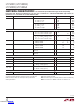
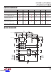
Pin FunctionS
Mode control
PIN NAME
PIN NUMBER
COMMENTS
2801
2802
2803
2804
2803-1
2804-1
V
CC
3 5 5 Input Supply (1.8V-5.5V). Bypass to GND with a 1µF capacitor.
V
DD
4 6 6 Generated Positive Supply Voltage for RS-232 Driver (7V). Connect a 1µF capacitor between
V
DD
and GND.
V
EE
13* 17* 9 Generated Negative Supply Voltage for RS-232 Driver (–6.3V). Connect a 1µF capacitor
between V
EE
and GND.
SW 5 7 7 Switch Pin. Connect a 10µH inductor between SW and V
CC
.
GND 6 8 8 Ground.
CAP 7 9 10 Charge Pump Capacitor for Generated Negative Supply Voltage. Connect a 220nF capacitor
between CAP and SW.
V
L
10 12 12 Logic Supply (1.8V-5.5V) for the receiver outputs, driver inputs, and control inputs. This pin
should be bypassed to GND with a 220nF capacitor if it’s not tied to V
CC
.
TIN (T1IN, T2IN) 11 14, 13 14, 13 Driver Input(s), referenced to V
L
.
TOUT (T1OUT, T2OUT) 2 3, 4 3, 4 RS-232 Driver Output(s).
RIN (R1IN, R2IN) 1 1, 2 1, 2 RS-232 Receiver Input(s). Includes internal 5kΩ termination resistor(s).
ROUT (R1OUT, R2OUT) 12 16, 15 16, 15 Receiver Output(s), referenced to V
L
. Output is short-circuit protected to GND/V
CC
/V
L
, and is
high impedance in Shutdown mode, allowing data line sharing.
PS 8 10 — Power Supply control pin, referenced to V
L
. Enables the integrated DC-DC converter.
MODE 9 11 — Mode control pin, referenced to V
L
. See Table 1 for functionality.
ON/OFF — — 11 Transceiver enable pin, referenced to V
L
. A logic low puts the device in Shutdown mode and
places both driver and receiver outputs in a high impedance state.
*Backside thermal pad
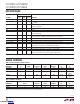
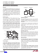
Table 1. LTC2801, LTC2802, LTC2803, LTC2804
MODE NAME PS MODE
RECEIVER
OUTPUT(S) DC-DC
DRIVER
OUTPUT(S) I
VCC
* I
VL
*
SHUTDOWN L L HI-Z OFF HI-Z 1µA 1µA
RECEIVER(S) ACTIVE L H ON OFF HI-Z 1µA 15µA
DRIVER(S) DISABLED H L ON ON HI-Z 2.1mA 80µA OR
150µA
NORMAL H H ON ON ON 2.3mA 80µA OR
150µA
Table 2. LTC2803-1, LTC2804-1
MODE NAME ON/OFF
RECEIVER
OUTPUTS DC-DC
DRIVER
OUTPUTS I
VCC
* I
VL
*
SHUTDOWN L HI-Z OFF HI-Z 1µA 1µA
NORMAL H ON ON ON 2.3mA 150µA
*Typical currents for static drivers. Normal mode currents are for unloaded outputs.
Downloaded from Arrow.com.Downloaded from Arrow.com.Downloaded from Arrow.com.Downloaded from Arrow.com.Downloaded from Arrow.com.Downloaded from Arrow.com.Downloaded from Arrow.com.Downloaded from Arrow.com.