
Datasheet

20
LTC2847
sn2847 2847fs
LT/TP 0603 1K • PRINTED IN USA
LINEAR TECHNOLOGY CORPORATION 2003
RELATED PARTS
PART NUMBER DESCRIPTION COMMENTS
LTC1321 Dual RS232/RS485 Transceiver Two RS232 Driver/Receiver Pairs or Two RS485 Driver/Receiver Pairs
LTC1334 Single 5V RS232/RS485 Multiprotocol Transceiver Two RS232 Driver/Receiver or Four RS232 Driver/Receiver Pairs
LTC1343 Software-Selectable Multiprotocol Transceiver 4-Driver/4-Receiver for Data and Clock Signals
LTC1344A Software-Selectable Cable Terminator Perfect for Terminating the LTC1543 (Not Needed with LTC1546)
LTC1345 Single Supply V.35 Transceiver 3-Driver/3-Receiver for Data and Clock Signals
LTC1346A Dual Supply V.35 Transceiver 3-Driver/3-Receiver for Data and Clock Signals
LTC1543 Software-Selectable Multiprotocol Transceiver Terminated with LTC1344A for Data and Clock Signals, Companion to
LTC1544 or LTC1545 for Control Signals
LTC1544 Software-Selectable Multiprotocol Transceiver Companion to LTC1546 or LTC1543 for Control Signals Including LL
LTC1545 Software-Selectable Multiprotocol Transceiver 5-Driver/5-Receiver Companion to LTC1546 or LTC1543
for Control Signals Including LL, TM and RL
LTC1546 Software-Selectable Multiprotocol Transceiver 3-Driver/3-Receiver with Termination for Data and Clock Signals
LTC2844 3.3V Software-Selectable Multiprotocol Transceiver Companion to LTC2846 for Control Signals Including LL
LTC2845 3.3V Software-Selectable Multiprotocol Transceiver 5-Driver/5-Receiver Companion to LTC2846 or LTC2847 for Control
Signals Including LL, TM and RL
LTC2846 3.3V Software-Selectable Multiprotocol Transceiver 3.3V Supply, 3-Driver/3-Receiver with Termination for Data and Clock
Signals, Generates the Required 5V and ±8V Supplies for LTC2846
Companion Parts
Linear Technology Corporation
1630 McCarthy Blvd., Milpitas, CA 95035-7417
(408) 432-1900
●
FAX: (408) 434-0507
●
www.linear.com
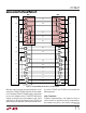
The V.11 drivers are driven between V
CC
and GND while
the V.10 drivers are driven between V
CC
and V
EE
. Assume
that the V.11 driver outputs are high and V.10 driver
outputs low. Current going into each 100Ω V.11 receiver
termination = (110mA – 2.7mA) – 23mA/3 = 28.1mA.
Current going into each 450Ω V.10 receiver termination =
23mA – 2mA/2 = 10.5mA. From Equation (2), V.11 P
RT
=
79mW and V.10 P
RT
= 49.6mW.
From Equation (3), P
DISS(2845)
= 5V • (110mA – 23mA) +
(8V • 0.3mA) + 5.5V • 23mA – 3 • 79mW – 2 • 49.6mW =
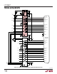
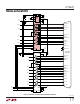
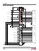
TYPICAL APPLICATIO S
U
228mW. Since the LTC2845 runs slow control signals, the
AC power dissipation can be assumed to be equal to the DC
power dissipation.
The extra power dissipated in the LTC2847 due to LTC2845
is given by Equation(4), P
DISS1(2847)
= 25% • (8V • 0.3mA)
+ 43% • (5.5V • 23mA) = 55mW. So for an X.21 DCE port
running at 10MBd, the LTC2847 dissipates approximately
718mW + 55mW = 773mW while the LTC2845 dissipates
228mW.