
Datasheet

LTC2854/LTC2855
11
285455fc
For more information www.linear.com/LTC2854
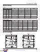
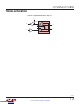
Switchable Termination
Proper cable termination is very important for good signal
fidelity. If the cable is not terminated with its characteristic
impedance, reflections will result in distorted waveforms.
The LTC2854/LTC2855 are the first 3.3V RS485/RS422
transceivers to offer integrated switchable termination
resistors on the receiver input pins. This provides the
advantage of being able to easily change, through logic
control, the line termination for optimal
performance when
configuring transceiver networks.
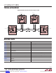
When the TE pin is high, the termination resistor is en-
abled and the differential resistance from A to B is 120Ω.
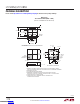
Figure10 shows the I/V characteristics between pins A
and B with the termination resistor enabled and disabled.
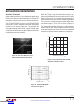
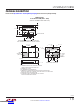
The resistance is maintained over the entire RS485 com-
mon mode range of –7V to +12V as shown in Figure 11.
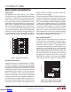
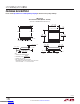
The integrated
termination resistor has a high frequency
response which does not limit performance at the maxi-
mum specified data rate. Figure 12 shows the magnitude
and phase of the termination impedance vs frequency.
Figure 10. Curve Trace Between A and B
with Termination Enabled and Disabled
Figure 11. Typical Resistance of the Enabled
Terminator vs Voltage on B Pin
Figure 12. Termination Magnitude
and Phase vs Frequency
10
–1
10
0
FREQUENCY (MHz)
MAGNITUDE (Ω)
PHASE (°)
10
1
80
95
110
125
140
155
170
185
–75
–60
–45
–30
–15
0
15
30
285455 F12
MAGNITUDE
PHASE
COMMON MODE VOLTAGE (V)
–10
RESISTANCE (Ω)
130
140
150
10
285455 F11
120
110
100
–5
0
5
15
V
AB
= 2V
APPLICATIONS INFORMATION
Downloaded from Arrow.com.Downloaded from Arrow.com.Downloaded from Arrow.com.Downloaded from Arrow.com.Downloaded from Arrow.com.Downloaded from Arrow.com.Downloaded from Arrow.com.Downloaded from Arrow.com.Downloaded from Arrow.com.Downloaded from Arrow.com.Downloaded from Arrow.com.