
Datasheet


LTC2856-1/LTC2856-2
LTC2857-1/LTC2857-2
LTC2858-1/LTC2858-2
12
285678ff
For more information www.linear.com/LTC2856-1
applicaTions inFormaTion
Driver
The driver provides full RS485 and RS422 compatibility.
When enabled, if DI is high, Y-Z is positive for the full-duplex
devices and A-B is positive for the half-duplex device.
When the driver is disabled, both outputs are high imped
-
ance. For
the full-duplex devices, the leakage on the driver
output pins
is guaranteed to be less than 10µA over the
entire common mode range of –7V to 12V. On the half-
duplex device, the impedance is dominated by the receiver
input resistance, R
IN
.
Driver Overvoltage and Overcurrent Protection
The driver outputs are protected from short circuits
to any voltage within the Absolute Maximum range of
(V
CC
– 15V) to 15V. The maximum current in this condition
is 250mA. If the pin voltage exceeds about ±10V, current
limit folds back to about half of the peak value to reduce
overall power dissipation and avoid damaging the part.
All devices also feature thermal shutdown protection that
disables the driver and receiver output in case of excessive
power dissipation (see Note 4).
Slew Limiting for EMI Emissions Control
The LTC2856-2, LTC2857-2 and the LTC2858-2 feature
reduced slew rate driver outputs to control the high fre
-
quency EMI emissions from equipment and data cables.
These devices
are limited to data rates of 250kbaud or
less. Slew limiting also mitigates the adverse affects of
imperfect transmission line termination caused by stubs
or mismatched cable.
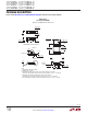
Figures 10 and 11 show the output waveforms from the
LTC2858-1 and its slew rate limited counterpart, the
LTC2858-2, operating at 250kbps. The corresponding
frequency spectrums show significant reduction in the
high frequency harmonics for the slew rate limited device.
Receiver and Failsafe
With the receiver enabled, when the absolute value of the
differential voltage between the A and B pins is greater than
200mV, the state of RO will reflect the polarity of (A-B).
These parts have a failsafe feature that guarantees the
receiver output to be in a logic-high state when the inputs
are either shorted, left open or terminated, but not driven
for more than about 3µs. The delay prevents signal zero
crossings from being interpreted as shorted inputs and
causing RO to go high inadvertently. This failsafe feature
is guaranteed to work for inputs spanning the entire com
-
mon mode range of –7V to 12V.
The
receiver
output is internally driven high (to V
CC
) or
low (to ground) with no
external pull-up needed. When
the receiver is disabled the RO pin becomes high-Z with
leakage of less than ±1µA for voltages within the supply
range.
Receiver Input Resistance
The receiver input resistance from A or B to ground is
guaranteed to be greater than 96k (C, I-Grade). This is 8×
higher than the requirements for the RS485 standard and
thus this receiver represents a one-eighth unit load. This,
in turn, means that 8× the standard number of receivers,
or 256 total, can be connected to a line without loading
it beyond what is called out in the RS485 standard. The
receiver input resistance from A or B to ground on high
temperature H-Grade parts is greater than 48k providing
a one-quarter unit load. The input resistance of the receiv
-
ers is
unaffected by enabling/disabling the receiver and
by powering/unpowering the part.
Supply Current
The unloaded
static supply currents in these devices are
very low—typically under 700µA for all modes of opera
-
tion. In
applications with resistively terminated cables,
the supply
current is dominated by the driver load. For
example, when using two 120Ω terminators with a dif
-
ferential driver output voltage of 2V, the DC load current
is 33mA, which is sourced by the positive voltage supply.
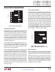
Power supply current increases with toggling data due to
capacitive loading and this term can increase significantly
at high data rates. Figure 8 shows supply current vs data
rate for two different capacitive loads for the circuit con
-
figuration of Figure 4.