
Datasheet

LTC2862/LTC2863/
LTC2864/LTC2865
16
2862345fc
For more information www.linear.com/LTC2862
The 250kbps mode has the added advantage of reducing
signal reflections in an unterminated network, and there-
by increasing the length of a network that can be used
without termination. Using the rule of thumb that the rise
time of the transmitter should be greater than four times
the one-way delay of the signal, networks of up to 140
feet can be driven without termination.
PROFIBUS Compatible Interface
PROFIBUS is an RS485-based field bus. In addition
to the specifications of TIA/EIA-485-A, the PROFIBUS
specification contains additional requirements for cables,
interconnects, line termination, and signal levels. The
following discussion applies to the PROFIBUS Type A cables
with associated connectors and termination. The Type A
cable is a twisted pair shielded cable with a characteristic
impedance of 135Ω to 165Ω and a loop resistance of
< 110Ω/km.
The LTC2865 family of RS485 transceivers may be used
in
PROFIBUS compatible equipment if the following
considerations are implemented. (Please refer to the
schematic of the PROFIBUS Compatible Interface in the
Typical Applications Section.)
1. The polarity of the PROFIBUS signal is opposite to the
polarity convention used in this data sheet. The PRO
-
FIBUS B wire is driven by a non-inverted signal, while
the
A wire is driven by an inverted signal. Therefore,
it is necessary to swap the output connections from
the transceiver. Pin A is connected to the PROFIBUS B
wire, and Pin B is connected to the PROFIBUS A wire.
2. Each end of the PROFIBUS line is terminated with a
220Ω resistor between B and A, a 390Ω pull-up resis
-
tor between B and V
CC
, and a 390Ω pull-down resistor
be-tween A and GND. This provides suitable termination
for the 150Ω twisted pair transmission cable.
3. The peak to peak differential voltage V
OD
received at
the end of a 100m cable with the cable and termina-
tions described
above must be greater than 4V and less
than 7V. The LTC2865 family produces signal levels in
excess of 7V when driving this network directly. 8.2Ω
resistors may be inserted between the A and B pins of
the transceiver and the B and A pins of the PROFIBUS
cable to attenuate the transmitted signal to meet the
PROFIBUS upper limit of 7V while still providing enough
drive strength to meet the lower limit of 4V.
4. The LTC2865 family transceiver should be powered by
a 5% tolerance 5V supply (4.75V
to 5.25
V) to ensure
that the PROFIBUS V
OD
tolerances are met.
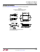
Auxiliary Protection For IEC Surge, EFT and ESD
An interface transceiver used in an industrial setting
may be exposed to extremely high levels of electrical
overstress due to phenomena such as lightning surge,
electrical fast transient (EFT) from switching high current
inductive loads, and electrostatic discharge (ESD) from
the discharge of electrically charged personnel or equip-
ment. Test methods to evaluate immunity of electronic
equipment to these phenomenon are defined in the IEC
standards 61000-4-2, 61000-4-4, and 61000-4-5, which
address ESD, EFT, and surge, respectively. The transi-
ents produced by the EFT and particularly the surge tests
contain much more energy than the ESD transients. The
LTC2865 family is designed for high robustness against
ESD, but the on-chip protection is not able to absorb the
energy associated with the 61000-4-5 surge transients.
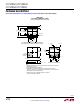
Therefore, a properly designed external protection network
is necessary to achieve a high level of surge protection,
and can also extend the ESD and EFT performance of the
LTC2865 family to extremely high levels.
In addition to providing surge, EFT and ESD protection,
an external network should preserve or extend the ability
of the LTC2865 family to withstand
overvoltage faults,
operate
over a wide common mode, and communicate
at high frequencies. In order to meet the first two
requirements, protection components with suitably high
conduction voltages must be chosen. A means to limit
current must be provided to prevent damage in case
a secondary protection device or the ESD cell on the
LTC2865 family fires and conducts. The capacitance of
these components must be kept low in order to permit high
frequency communication over a network with multiple
nodes. Meeting the requirements for conducting very high
energy electrical transients while maintaining high hold-off
voltages and low capacitance is a considerable challenge.
applicaTions inForMaTion