
Datasheet


LTC2862/LTC2863/
LTC2864/LTC2865
15
2862345fc
For more information www.linear.com/LTC2862
exacerbated by capacitive loading. If a logic input is held
near its threshold (typically V
CC
/2 or V
L
/2), a noise glitch
from a driver transition may exceed the hysteresis levels on
the logic and data input pins, causing an unintended state
change. This can be avoided by maintaining normal logic
levels on the pins and by slewing inputs faster than 1V/
μs. Good supply decoupling and proper driver termination
also reduce glitches caused by driver transitions.
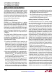
RS485 Cable Length vs Data Rate
Many factors contribute to the maximum cable length
that can be used for RS485 or RS422 communication,
including driver transition times, receiver threshold, duty
cycle distortion, cable properties and data rate. A typical
curve of cable length versus maximum data rate is shown
in Figure 9. Various regions of this curve reflect different
performance limiting factors in data transmission.
At frequencies below 100kbps, the maximum cable length is
determined by DC resistance in the cable. In this example,
a cable longer than 4000ft will attenuate the signal at the
far end to less than what can be reliably detected by the
receiver.
For data rates above 100kbps the capacitive and inductive
properties of the cable begin to dominate
this relationship.
The attenuation of the cable is frequency and length
dependent, resulting in increased rise and fall times at
the far end of the cable. At high data rates or long cable
applicaTions inForMaTion
lengths, these transition times become a significant part
of the signal bit time. Jitter and intersymbol interference
aggravate this so that the time window for capturing valid
data at the receiver becomes impossibly small.
The boundary at 20Mbps in Figure 9 represents the
guaranteed maximum operating rate of the LTC2862
series. The dashed vertical line at 10Mbps represents the
specified maximum data rate in the RS485 standard. This
boundary is not a limit, but reflects the maximum data
rate that the specification was written for.
It should be emphasized that the plot in Figure 9 shows
a typical relation between maximum data rate and
cable length. Results with the LTC2862 series will vary,
depending on cable properties such as conductor gauge,
characteristic impedance, insulation material, and solid
versus stranded conductors.
Low EMI 250kbps Data Rate
The LTC2862-2, LTC2863-2, and the LTC2864-2 feature
slew rate limited transmitters for low electromagnetic
interference (EMI) in sensitive applications. In addition,
the LTC2865 has a logic-selectable 250kbps transmit rate.
The slew rate limit circuit maintains consistent control of
transmitter slew rates across voltage and temperature to
ensure low EMI under all operating conditions. Figure 10
demonstrates the reduction in high frequency content
achieved by the 250kbps mode compared to the 20Mbps
mode.
Figure 9. Cable Length vs Data Rate (RS485/RS422 Standard
Shown in Vertical Solid Line)
Figure 10. High Frequency EMI Reduction of Slew Limited
250kbps Mode Compared to Non Slew Limited 20Mbps Mode
DATA RATE (bps)
10k
10
CABLE LENGTH (FT)
100
1k
10k
100k 1M 10M
2862345 F09
100M
LOW EMI
MODE
SLO = GND
RS485
STANDARD
SPEC
FREQUENCY (MHz)
0
–120
Y–Z (NON SLEW LIMITED) (dB)
–40
–60
–80
–100
–20
0
20
–60
Y–Z (SLEW LIMITED) (dB)
20
0
–20
–40
40
60
80
2
4 6 8 10
2862345 F10
12
NON SLEW LIMITED
SLEW LIMITED