
Datasheet

LTC2870/LTC2871
10
28701fb
For more information www.linear.com/LTC2870
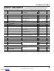
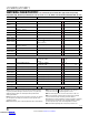
pin FuncTions
PIN NAME
LTC2870
QFN
LTC2870
TSSOP
LTC2871
QFN
LTC2871
TSSOP
DESCRIP
TION
V
CC
16, 20, 24 19, 23, 27 21, 27, 33 25, 31, 37 Input Supply (3V to 5.5V). Tie all three pins together and connect a 2.2µF or larger capacitor
between V
CC
(adjacent to V
DD
) and GND.
V
L
25 28 35 1 Logic Supply (1.7V to 5.5V) for the receiver outputs, driver inputs, and control inputs. Bypass
this pin to GND with a 0.1µF capacitor if not tied tot V
CC
. Keep V
L
≤ V
CC
for proper operation.
However, V
L
> V
CC
will not damage the device, provided that absolute maximum limits are
respected.
V
DD
15 18 20 24 Generated Positive Supply Voltage for RS232 Driver (+7V). Connect 1μF capacitor between
V
DD
and GND.
V
EE
1, 12, 29 4, 15, 29 1, 12, 16,
19, 39
5, 16, 20,
23, 39
Generated Negative Supply Voltage for RS232 Driver (–6.3V). Tie all pins together and connect
1μF capacitor between V
EE
(the V
EE
pin sequentially after CAP) and GND.
GND 10, 13,
18, 23
13, 16,
21, 26
14, 17,
25, 32
18, 21,
29, 36
Ground. Tie all four pins together
.
CAP 11 14 15 19 Charge Pump Capacitor for Generated Negative Supply Voltage. Connect a 220nF capacitor
between CAP and SW.
SW 14 17 18 22 Switch Pin. Connect 10µH inductor between SW and V
CC
.
A 22 25 29 33 RS485 Positive Receiver Input (Full-Duplex Mode) or RS232 Receiver Input 1 (LTC2870).
B 21 24 28 32 RS485 Negative Receiver Input (Full-Duplex Mode) or RS232 Receiver Input 2 (LTC2870).
RA 2 5 RS485 Differential Receiver Output or RS232 Receiver Output 1.
RB 3 6 RS232 Receiver Output 2.
RO 34 38 RS485 Differential Receiver Output.
RIN1 31 35 RS232 Receiver Input 1.
RIN2 30 34 RS232 Receiver Input 2.
ROUT1 2 6 RS232 Receiver Output 1.
ROUT2 3 7 RS232 Receiver Output 2.
DIN1 8 12 RS232 Driver Input 1. Do not float.
DIN2 9 13 RS232 Driver Input 2. Do not float.
DOUT1 23 27 RS232 Driver Output 1.
DOUT2 22 26 RS232 Driver Output 2.
DI 7 11 RS485 Driver Input. Do not float.
DY 7 10 RS485 Driver Input or RS232 Driver Input 1. Do not float.
DZ 8 11 RS232 Driver Input 2. Do not float.
Y 19 22 26 30 RS485 Positive Driver Output. RS232 Driver Output 1 (LTC2870).
RS485 Positive Receiver Input (LTC2870 or LTC2871 in Half-Duplex Mode).
Z 17 20 24 28 RS485 Negative Driver Output or RS232 Driver Output 2 (LTC2870).
RS485 Negative Receiver Input (LTC2870 or LTC2871 in Half-Duplex Mode).
Downloaded from Arrow.com.Downloaded from Arrow.com.Downloaded from Arrow.com.Downloaded from Arrow.com.Downloaded from Arrow.com.Downloaded from Arrow.com.Downloaded from Arrow.com.Downloaded from Arrow.com.Downloaded from Arrow.com.Downloaded from Arrow.com.