
Datasheet

LTC2870/LTC2871
22
28701f
APPLICATIONS INFORMATION
Receiver Outputs
The RS232 and RS485 receiver outputs are internally
driven high (to V
L
) or low (to GND) with no external pull-
up needed. When the receivers are disabled the output pin
becomes Hi-Z with leakage of less than ±5A for voltages
within the V
L
supply range.
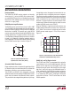
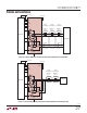
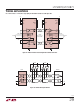
RS485 Receiver Input Resistance
The RS485 receiver input resistance from A or B to GND
(Y or Z to GND in half-duplex mode with driver disabled) is
greater than 96k (typically 125k) when the integrated
termination is disabled. This permits up to a total of 256
receivers per system without exceeding the RS485 receiver
loading specification. The input resistance of the receiver
is unaffected by enabling/disabling the receiver or whether
the part is in half-duplex, full-duplex, loopback mode, or
even unpowered. The equivalent input resistance looking
into the RS485 receiver pins is shown in Figure 17.
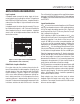
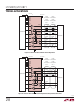
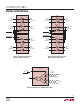
Figure 18. Typical Resistance of the Enabled RS485
Terminator vs Common Mode Voltage on A /B
through logic control, the proper line termination for cor-
rect operation when configuring transceiver networks.
Termination should be enabled on transceivers positioned
at both ends of the network bus. Termination on the driver
nodes is important for cases where the driver is disabled
but there is communication on the connecting bus from
another node. Differential termination resistors are never
enabled in RS232 mode on the LTC2870.
When the TE485 pin is high, the termination resistors are
enabled and the differential resistance from A to B and Y
to Z is 120. The resistance is maintained over the entire
RS485 common mode range of –7V to 12V as shown in
Figure 18.
Figure 17: Equivalent RS485 Receiver
Input Resistance Into A and B (Note 5)
28701 F17
A
B
TE485
60
60
125k
125k
Selectable RS485 Termination
Proper cable termination is important for good signal fidel-
ity. When the cable is not terminated with its characteristic
impedance, reflections cause waveform distortion.
The LTC2870 and LTC2871 offer integrated switchable
120 termination resistors between the differential receiver
inputs and also between the differential driver outputs.
This provides the advantage of being able to easily change,
RS485 Half- and Full-Duplex Control
The LTC2870 and LTC2871 are equipped with a control to
switch between half- and full-duplex operation. With the
H/F pin set to a logic low, the A and B pins serve as the
differential receiver inputs. With the H/F pin set to a logic
high, the Y and Z pins serve as the differential inputs. In
either configuration, the RS485 driver outputs are always
on Y and Z. The impedance looking into the A and B pins
is not affected by H/F control, including the differential
termination resistance. The H/F control does not affect
RS232 operation.
VOLTAGE (V)
–10
RESISTANCE (Ω)
126
124
122
118
120
116
10–5
28701 F18
1550
V
CC
= 5.0V
V
CC
= 3.3V