
Datasheet

LTC2870/LTC2871
10
28701f
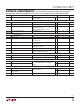
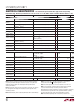
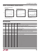
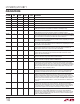
PIN FUNCTIONS
PIN NAME
LTC2870
QFN
LTC2870
TSSOP
LTC2871
QFN
LTC2871
TSSOP DESCRIPTION
DOUT1 23 27 RS232 Driver Output 1.
DOUT2 22 26 RS232 Driver Output 2.
DI 7 11 RS485 Driver Input.
DY 7 10 RS485 Driver Input or RS232 Driver Input 1.
DZ 8 11 RS232 Driver Input 2.
Y 19 22 26 30 RS485 Positive Driver Output. RS232 Driver Output 1 (LTC2870).
RS485 Positive Receiver Input (LTC2870 or LTC2871 in Half-Duplex Mode).
Z 17 20 24 28 RS485 Negative Driver Output or RS232 Driver Output 2 (LTC2870).
RS485 Negative Receiver Input (LTC2870 or LTC2871 in Half-Duplex Mode).
485/232 4 7 Interface Select Input. A logic low enables RS232 mode and a high enables RS485 mode.
The mode determines which transceiver inputs and outputs are accessible at the LTC2870
pins as well as which is controlled by the driver and receiver enable pins.
RXEN 5 8 Receiver Enable. A logic high disables RS232 and RS485 receivers leaving receiver
outputs Hi-Z. A logic low enables the RS232 or RS485 receivers, depending on the state
of the interface select input 485/232 .
DXEN 6 9 Driver Enable. A logic low disables the RS232 and RS485 drivers leaving the driver output
in a Hi-Z state. A logic high enables the RS232 or RS485 drivers, depending on the state
of the interface select input 485/232.
RX232 11 15 RS232 Receiver Enable. A logic high disables the RS232 receivers and input termination
resistors leaving the RS232 receiver outputs in a Hi-Z state. A logic low enables the
RS232 receivers and resistors, subject to the state of the CH2 pin.
RX485 5 9 RS485 Receiver Enable. A logic high disables the RS485 receiver leaving the RS485
receiver output in a Hi-Z state. A logic low enables the RS485 receiver and resistors,
subject to the state of the CH2 pin.
DX232 10 14 RS232 Driver Enable. A logic low disables the RS232 drivers leaving the RS232 driver
outputs in a Hi-Z state. A logic high enables the RS232 drivers.
DX485 6 10 RS485 Driver Enable. A logic low disables the RS485 driver leaving the RS485 driver
output in a Hi-Z state. A logic high enables the RS485 driver.
H/F 27 2 37 3 RS485 Half-Duplex Select Input. A logic low is used for full-duplex operation where pins
A and B are the receiver inputs and pins Y and Z are the driver outputs. A logic high is
used for half-duplex operation where pins Y and Z are both the receiver inputs and driver
outputs and pins A and B do not serve as the receiver inputs. The impedance on A and B
and state of differential termination between A and B is independent of the state of H/F.
The H/F pin has no effect on RS232 operation.
TE485 28 3 38 4 RS485 Termination Enable. A logic high enables a 120Ω resistor between pins A and
B and also between pins Y and Z. A logic low opens the resistors, leaving A/B and Y/Z
unterminated. The LTC2870 termination resistors are never enabled in RS232 mode.
FEN 9 12 13 17 Fast Enable. A logic high enables fast enable mode. In fast enable mode the integrated
DC/DC converter is active independent of the state of driver, receiver, and termination
enable pins allowing faster circuit enable times than are otherwise possible. A logic low
disables fast enable mode leaving the state of the DC/DC converter dependent on the state
of driver, receiver, and termination enable control inputs. The DC/DC converter powers
down only when FEN is low and all drivers, receivers, and terminators are disabled (refer
to Table 1).
LB 26 1 36 2 Loopback Enable. A logic high enables logic loopback diagnostic mode, internally routing
the driver input logic levels to the receiver output pins. This applies to both RS232
channels as well as the RS485 driver/receiver. The targeted receiver must be enabled for
the loopback signal to be available on its output. A logic low disables loopback mode. In
Loopback mode, signals are not inverted from driver inputs to receiver outputs.
CH2 4 8 RS232 Channel 2 Disable. A logic high disables RS232 receiver 2 and RS232 driver 2
independent of the state of RX232 and DX232 pins. In this state, the disabled driver
output becomes Hi-Z and the 5k load resistor on the disabled receiver input is opened.
A logic low allows both RS232 transceiver channels to be enabled or disabled together
based on the RX232 and DX232 pins.