
Datasheet


LTC2870/LTC2871
21
28701f
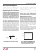
Figure 15. RS485 Receiver Input Threshold Characteristics
APPLICATIONS INFORMATION
All devices also feature thermal shutdown protection that
disables the drivers, receivers, and RS485 terminators in
case of excessive power dissipation (see Note 6).
RS485 Balanced Receiver with Full Failsafe Operation
The LTC2870 and LTC2871 receivers use a window com-
parator with two voltage thresholds centered around zero
for low pulse width distortion. As illustrated in Figure 15, for
a differential signal approaching from a negative direction,
the threshold is typically +65mV. When approaching from
the positive direction, the threshold is typically –65mV. Each
of these thresholds has about 25mV of hysteresis (not
shown in the figure). The state of RO reflects the polarity
of A–B in full-duplex mode or Y–Z in half-duplex mode.
This windowing around 0V preserves pulse width and
duty cycle for small input signals with heavily slewed
edges, typical of what might be seen at the end of a very
long cable. This performance is highlighted in Figure 16,
where a signal is driven through 4000 feet of CAT5e cable at
3Mbps. Even though the differential signal peaks at just over
±100mV and is heavily slewed, the output maintains a nearly
perfect signal with almost no duty cycle distortion.
An additional benefit of the window comparator architecture
is excellent noise immunity due to the wide effective dif-
ferential hysteresis (or ‘AC’ hysteresis) of about 130mV for
normal signals transitioning through the window region in
less than approximately 2µs. Increasingly slower signals
will have increasingly less effective hysteresis, limited by
the DC failsafe value of about 25mV.
The LTC2870 and LTC2871 provide full failsafe operation
that guarantees the receiver output will be a logic high
state when the inputs are shorted, left open, or terminated
but not driven, for more than about 2µs. The delay allows
normal data signals to transition through the threshold
region without being interpreted as a failsafe condition.
RS485 Biasing Resistors Not Required
RS485 networks are often biased with a resistive divider
to generate a differential voltage of ≥200mV on the data
lines, which establishes a logic high state when all the
transmitters on the network are disabled. The values of
the biasing resistors depend on the number and type
of transceivers on the line and the number and value of
terminating resistors. Therefore the values of the biasing
resistors must be customized to each specific network
installation, and may change if nodes are added to or
removed from the network.
The internal failsafe feature of the LTC2870 and LTC2871
eliminates the need for external biasing resistors. The
LTC2870 and LTC2871 transceivers will operate correctly
on unbiased, biased or underbiased networks.
28701 F15
RECEIVER
OUTPUT LOW
–200mV –65mV 0V
RO
65mV 200mV
V
AB
RECEIVER
OUTPUT HIGH
Figure 16. A 3Mbps Signal Driven Down 4000ft of CAT 5e
Cable. Top Traces: Received Signals After Transmission
Through Cable; Middle Trace: Math Showing Differences
of Top Two Signals; Bottom Trace: Receiver Output
0.1V/DIV
0.1V/DIV
5V/DIV
28701 F16
200ns/DIV
RO
(A-B)
A
B