
Datasheet


LTC2872
20
2872f
applicaTions inForMaTion
Selectable RS485 Termination
Proper cable termination is important for good signal fidel-
ity. When the cable is not terminated with its characteristic
impedance, reflections cause waveform distortion.
The LTC2872 offers integrated switchable 120Ω termination
resistors between the differential receiver inputs and also
between the differential driver outputs. This provides the
advantage of being able to easily change, through logic
control, the proper line termination for correct operation
when configuring transceiver networks. Termination should
be enabled on transceivers positioned at both ends of a
network bus.
Termination on the driver nodes is important for cases
where the driver is disabled but there is communication on
the connecting bus from another node. Driver termination
across Y and Z can be disabled independently from the
termination across A and B by setting DZ low. See Table 7
for details.
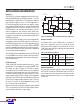
The termination resistance is maintained over the entire
RS485 common mode range of –7V to 12V as shown in
Figure 18. The voltage across pins with the terminating
resistor enabled should not exceed 6V as indicated in the
Absolute Maximum Ratings table.
Figure 18. Typical Resistance of the Enabled RS485
Terminator vs Common Mode Voltage of A and B
the differential receiver inputs. With the H/F pin set to
a logic-high, the Y and Z pins serve as the differential
inputs. In either configuration, the RS485 driver outputs
are always on Y and Z. The impedance looking into the
A and B pins is not affected by H/F control, including the
differential termination resistance. The H/F control does
not affect RS232 operation.
Logic Loopback
A loopback mode connects the driver inputs to the re-
ceiver outputs (noninverting) for self test. This applies
to both RS232 and RS485 transceivers. Loopback mode
is entered when the LB pin is set to a logic-high and the
relevant receiver is enabled.
In loopback mode, the drivers function normally. They
can be disabled with output in a Hi-Z state or left enabled
to allow loopback testing in normal operation. Loopback
works in half- or full-duplex modes and does not affect
the termination resistors.
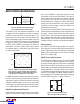
RS485 Cable Length vs Data Rate
Many factors contribute to the maximum cable length
that can be used for for RS485 or RS422 communication,
including driver transition times, receiver threshold, duty
cycle distortion, cable properties and data rate. A typical
curve of cable length versus maximum data rate is shown
in Figure 19. Various regions of this curve reflect different
performance limiting factors in data transmission.
Figure 19. Cable Length vs Data Rate (RS485/RS422
Standard Shown in Vertical Solid Line)
RS485 Half- and Full-Duplex Control
The LTC2872 is equipped with a control to change the RS485
transceiver operation from full-duplex to half-duplex. With
the H/F pin set to a logic-low, the A and B pins serve as
DATA RATE (bps)
CABLE LENGTH (FT)
2872 F19
10k
1k
100
10
10k 10M 100M1M100k
LTC2872
MAX DATA RATE
RS485/RS422
MAX DATA RATE
VOLTAGE (V)
–10
RESISTANCE (Ω)
126
124
122
118
120
116
10–5
2872 F18
1550
V
CC
= 5.0V
V
CC
= 3.3V
Downloaded from Arrow.com.Downloaded from Arrow.com.Downloaded from Arrow.com.Downloaded from Arrow.com.Downloaded from Arrow.com.Downloaded from Arrow.com.Downloaded from Arrow.com.Downloaded from Arrow.com.Downloaded from Arrow.com.Downloaded from Arrow.com.Downloaded from Arrow.com.Downloaded from Arrow.com.Downloaded from Arrow.com.Downloaded from Arrow.com.Downloaded from Arrow.com.Downloaded from Arrow.com.Downloaded from Arrow.com.Downloaded from Arrow.com.Downloaded from Arrow.com.Downloaded from Arrow.com.