
Datasheet


LTC2872
8
2872f
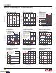
pin FuncTions
V
CC
(Pins 1, 21, 31): Input Supply (3.0V to 5.5V). Tie all
three pins together and connect 2.2µF capacitor between
VCC and GND.
V
L
(Pin 35): Logic Supply (1.7V to 5.5V) for the receiver
outputs, driver inputs, and control inputs. This pin should
be bypassed to GND with a 0.1µF capacitor if it is not tied
to V
CC
. V
L
must be less than or equal to V
CC
for proper
operation.
V
DD
(Pin 20): Generated Positive Supply Voltage for RS232
Driver (7V). Connect 2.2µF capacitor between V
DD
and GND.
V
EE
(Pin 39):Generated Negative Supply Voltage for RS232
Driver (–6.3V). Tie all pins together and connect 2.2µF
capacitor between V
EE
and GND.
GND (Pins 5, 18, 27, 34): Ground. Tie all four pins together.
CAP (Pin 17): Charge Pump Capacitor for Generated Nega-
tive Supply Voltage. Connect a 470nF capacitor between
CAP and SW.
SW (Pin 19): Switch Pin. Connect 22µH inductor between
SW and V
CC
.
A1 (Pin 2): RS485 Differential Receiver #1 Positive Input
(Full-Duplex Mode) or RS232 Receiver #1a Input.
A2 (Pin 30): RS485 Differential Receiver #2 Positive Input
(Full-Duplex Mode) or RS232 Receiver #2a Input.
B1 (PIn 3): RS485 Differential Receiver #1 Negative Input
(Full-Duplex Mode) or RS232 Receiver #1b Input.
B2 (Pin 29): RS485 Differential Receiver #1 Negative Input
(Full-Duplex Mode) or RS232 Receiver #2b Input.
RA1 (Pin 37): RS485 Differential Receiver #1 Output or
RS232 Receiver #1a Output.
RA2 (Pin 33): RS485 Differential Receiver #2 Output or
RS232 Receiver #2a Output.
RB1 (Pin 38): RS232 Receiver #1b Output.
RB2 (Pin 32): RS232 Receiver #2b Output.
DY1 (Pin 7): RS485 Differential Driver #1 Input or RS232
Driver #1y Input.
DY2 (Pin 25): RS485 Differential Driver #2 Input or RS232
Driver #2y Input.
DZ1 (Pin 8): RS232 Driver #1z Input.
DZ2 (Pin 24): RS232 Driver #2z Input.
Y1 (Pin 4): RS485 Differential Driver #1 Positive Output
or RS232 Driver #1y Output, RS485 Differential Receiver
#1 Positive Input (Half-Duplex Mode).
Y2 (Pin 28): RS485 Differential Driver #2 Positive Output
or RS232 Driver #2y Output, RS485 Differential Receiver
#2 Positive Input (Half-Duplex Mode).
Z1 (Pin 6): RS485 Differential Driver #1 Negative Output
or RS232 Driver #1z Output, RS485 Differential Receiver
#1 Negative Input (Half-Duplex Mode).
Z2 (Pin 26): RS485 Differential Driver #2 Negative Output
or RS232 Driver #2z Output, RS485 Differential Receiver
#2 Negative Input (Half-Duplex Mode).
485/232_1 (Pin 13): Interface Select #1 Input. A logic low
enables RS232 mode and a high enables RS485 mode for
transceiver #1. The mode determines which transceiver
inputs and outputs are accessible at the LTC2872 pins
as well as which is controlled by the driver and receiver
enable pins.
485/232_2 (Pin 14): Interface Select #2 Input. A logic low
enables RS232 mode and a high enables RS485 mode for
transceiver #2. The mode determines which transceiver
inputs and outputs are accessible at the LTC2872 pins
as well as which is controlled by the driver and receiver
enable pins.
RXEN1 (Pin 9): Receivers #1 Enable. A logic high disables
RS232 and RS485 receivers in transceiver #1, leaving their
outputs Hi-Z. A logic low enables the RS232 or RS485
receivers in transceiver #1, depending on the state of the
Interface Select Input 485/232_1.
RXEN2 (Pin 23): Receivers #2 Enable. A logic high disables
RS232 and RS485 receivers in transceiver #2, leaving their
outputs Hi-Z. A logic low enables the RS232 or RS485
receivers in transceiver #2, depending on the state of the
Interface Select Input 485/232_2.
Downloaded from Arrow.com.Downloaded from Arrow.com.Downloaded from Arrow.com.Downloaded from Arrow.com.Downloaded from Arrow.com.Downloaded from Arrow.com.Downloaded from Arrow.com.Downloaded from Arrow.com.