
Datasheet

LTC2872
19
2872f
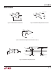
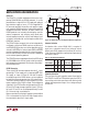
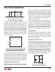
Figure 15. RS485 Receiver Input Threshold
Characteristics with Typical Values Shown
applicaTions inForMaTion
The benefit of this dual threshold architecture is that
it supports full failsafe operation yet offers a balanced
threshold, centered on 0V, for normal data signals. This
balance preserves duty cycle for small input signals with
heavily slewed edges, typical of what might be seen at the
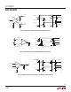
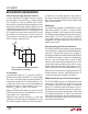
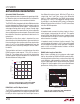
end of a very long cable. This performance is highlighted
in Figure 16, where a signal is driven through 4000 feet
of CAT5e cable at 3Mbps. Even though the differential
signal peaks at just over 100mV and is heavily slewed,
the output maintains a nearly perfect signal with almost
no duty cycle distortion.
lines, which establishes a logic-high state when all the
transmitters on the network are disabled. The values of
the biasing resistors depend on the number and type
of transceivers on the line and the number and value of
terminating resistors. Therefore, the values of the biasing
resistors must be customized to each specific network
installation, and may change if nodes are added to or
removed from the network.
The internal failsafe feature of the LTC2872 eliminates the
need for external network biasing resistors provided they
are used in a network of transceivers with similar internal
failsafe features. This also allows the network to support a
high number of nodes, up to 256, by eliminating the bias
resistor loading. The LTC2872 transceivers will operate
correctly on biased, unbiased, or under-biased networks.
Receiver Outputs
The RS232 and RS485 receiver outputs are internally
driven high (to V
L
) or low (to GND) with no external pull-up
needed. When the receivers are disabled, the output pin
becomes Hi-Z with leakage of less than ±5μA for voltages
within the V
L
supply range.
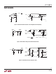
RS485 Receiver Input Resistance
The RS485 receiver input resistance from A or B to GND
(Y or Z to GND in half-duplex mode with driver disabled)
is greater than 96k (typically 125k) when the integrated
termination is disabled. This permits up to a total of 256
receivers per system without exceeding the RS485 receiver
loading specification. The input resistance of the receiver
is unaffected by enabling/disabling the receiver or whether
the part is in half-duplex, full-duplex, loopback mode, or
even unpowered. The equivalent input resistance looking
into the RS485 receiver pins is shown in Figure 17.
Figure 16. A 3Mbps Signal Driven Down 4000ft of CAT5e
Cable. Top Traces: Received Signals After Transmission
Through Cable; Middle Trace: Math Showing Differences
of Top Two Signals; Bottom Trace: Receiver Output
An additional benefit of the balanced architecture is excel-
lent noise immunity due to the wide effective differential
input signal hysteresis of 160mV for signals transitioning
through the window region in less than 2μs. Increasingly
slower signals will have increasingly less effective hyster-
esis, limited by the DC failsafe hysteresis of about 30mV.
RS485 Biasing Network Not Required
RS485 networks are often biased with a resistive divider
to generate a differential voltage of ≥200mV on the data
0.1V/DIV
0.1V/DIV
5V/DIV
2872 F16
200ns/DIV
RA
(A-B)
A
B
Figure 17. Equivalent RS485 Receiver
Input Resistance Into A and B (Note 5)
2872 F17
A
B
TE485
60Ω
60Ω
125k
125k
2872 F15
–80mV –50mV 0V
RA
80mV
V
AB
(NOTE 5)
RISING THRESHOLD
SHIFTS IF SIGNAL IS
IN WINDOW > ~2µs
TO SUPPORT
FAILSAFE