
Datasheet


LTC2909
12
2909fb
For a positive-monitoring application, R
P2
is then chosen
by:
R
P2
= R
P1
(2V
TRIP
– 1)
For a negative-monitoring application:
R
N2
= R
N1
(1 – 2V
TRIP
)
Note that the value V
TRIP
should be negative for a nega-
tive application.
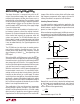
The LTC2909 can also be used to monitor a single supply
for both UV and OV. This may be accomplished with three
resistors, instead of the four required for two independent
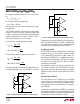
supplies. Confi gurations are shown in Figures 3 and 4.
R
P4
or R
N4
may be chosen as is R
P1
above.
For a given R
P4
, monitoring a positive supply:
RR
VV
V
RRV
V
V
PP
OV UV
UV
PPUV
OV
UV
54
64
21
=
=
()
–
–
For monitoring a negative supply with a given R
N4
:
RR
VV
V
RR V
V
V
NN
UV OV
UV
NN UV
OV
U
54
64
1
12
1
1
=
=
()
–
–
–
–
–
VV
For example, consider monitoring a –5V supply at ±10%. For
this supply application: V
OV
= –5.575V and V
UV
= –4.425V.
Suppose we wish to consume about 5A in the
divider, so
R
N4
= 100k. We then fi nd R
N5
= 21.0k, R
N6
= 1.18M (nearest
1% standard values have been chosen). Suggested values
of resistors for 5% monitoring are shown in Table 3.
V
CC
Monitoring/UVLO
The LTC2909 contains an accurate third 10% undervoltage
monitor on the V
CC
pin. This monitor is fi xed at a nominal
11.5% below the V
CC
specifi ed in the part number. The
standard part (LTC2909-2.5) is confi gured to monitor a
2.5V supply (UVLO threshold of 2.213V), but versions
to monitor 3.3V and 5.0V (UVLO of 2.921V and 4.425V,
respectively) are available.
For applications that do not need V
CC
monitoring, the
2.5V version should be used, and the UVLO will simply
guarantee that the V
CC
is above the minimum required for
proper threshold and timer accuracy before the timeout
begins.
Setting the Reset Timeout
The reset timeout of the LTC2909 may be confi gured
in one of three ways: internal 200ms, programmed by
external capacitor and no timeout (comparator mode).
The mode of the timer is determined by the connection
of the TMR pin.
In externally-controlled mode, the TMR pin is connected
by a capacitor to ground. The value of that capacitor allows
for selection of a timeout ranging from about 400s to 10
seconds. See the following section for details.
APPLICATIO S I FOR ATIO
WUU
U
–
+
–
+
+
–
0.5V
2909 F03
ADJ1
ADJ2
V
MON
R
P5
R
P6
R
P4
Figure 3. Setting UV and OV Trip Point for a Positive Supply
–
+
–
+
+
–
0.5V
2909 F04
ADJ2
ADJ1
REF
V
MON
R
N5
R
N4
R
N6
Figure 4. Setting UV and OV Trip Point for a Negative Supply