
Datasheet


LTC2913
7
2913fb
APPLICATIONS INFORMATION
Voltage Monitoring
The LTC2913 is a low power dual voltage monitoring
circuit with two undervoltage and two overvoltage inputs.
A timeout period that holds OV and UV asserted after all
faults have cleared is adjustable using an external capacitor
and is externally disabled.
Each voltage monitor has two inputs (VHn and VLn) for
detecting undervoltage and overvoltage conditions. When
confi gured to monitor a positive voltage V
n
using the
3-resistor circuit confi guration shown in Figure 1, VHn
is connected to the high side tap of the resistive divider
and VLn is connected to the low side tap of the resistive
divider.
3-Step Design Procedure
The following 3-step design procedure determines ap-
propriate resistances to obtain the desired UV and OV trip
points for the voltage monitor circuit in Figure 1.
For supply monitoring, V
n
is the desired nominal operat-
ing voltage, I
n
is the desired nominal current through the
resistive divider, V
OV
is the desired overvoltage trip point
and V
UV
is the desired undervoltage trip point.
1. Choose R
A
to obtain the desired OV trip point
R
A
is chosen to set the desired trip point for the
overvoltage monitor.
R
A
=
0.5V
I
n
•
V
n
V
OV
(1)
2. Choose R
B
to obtain the desired UV trip point
Once R
A
is known, R
B
is chosen to set the desired trip
point for the undervoltage monitor.
R
B
=
0.5V
I
n
•
V
n
V
UV
–R
A
(2)
3. Choose R
C
to complete the design
Once, R
A
and R
B
are known, R
C
is determined by:
R
C
=
V
n
I
n
–R
A
–R
B
(3)
If any of the variables V
n
, I
n
, V
UV
or V
OV
change, then each
step must be recalculated.
Voltage Monitor Example
A typical voltage monitor application is shown in Figure 2.
The monitored voltage is a 5V ±10% supply. Nominal cur-
rent in the resistive divider is 10μA.
1. Find R
A
to set the OV trip point of the monitor.
R
A
=
0.5V
10µA
•
5V
5.5V
45.3k
2. Find R
B
to set the UV trip point of the monitor.
R
B
=
0.5V
10µA
•
5V
4.5V
– 45.3k 10.2k
3. Determine R
C
to complete the design.
R
C
=
5V
10µA
– 45.3k 10.2k 442k
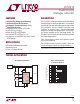
Figure 1. 3-Resistor Positive UV/OV Monitoring Confi guration Figure 2. Typical Supply Monitor
–
+
–
+
+
–
0.5V
LTC2913
UV
n
VHn
R
C
R
B
R
A
2913 F01
V
n
VLn
OV
n
VH1
R
C
442k
R
B
10.2k
R
A
45.3k
V
CC
GND
LTC2913
VL1
2913 F02
OV
UV
V
CC
5V
V1
5V ±10%