
Datasheet

LTC2951-1/LTC2951-2
15
295112fb
PowerPath
TM
Switching
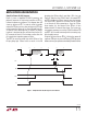
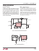
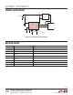
The EN open-drain output of the LTC2951-2 is designed
to switch on/off an external power PFET. This allows a
user to connect/disconnect a power supply (or battery)
to its load by toggling the PB pin. Figure 7 shows the
LTC2951-2 controlling a two cell Li-Ion battery application.
The INT and KILL pins are connected to the output of the
PFET through a resistor divider. The KILL pin serves as a
voltage monitor. When V
OUT
drops below 6V, the EN pin
is open-circuited 30µs later.
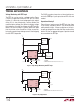
Figure 7. PowerPath Control with 6V Undervoltage Detect
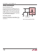
Figure 8. Filtering for Noisy PB Traces
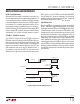
PB Pin in a Noisy Environment
The rugged PB pin is designed to operate in noisy envi-
ronments. Transients below ground (>–6V) and above V
IN
(<33V) will not damage the rugged PB pin. Additionally,
the PB pin can withstand ESD HBM strikes up to ±10kV.
In order to keep external noise from coupling inside the
LTC2951, place an RC network close to the PB pin. A 5k
resistor and a 0.1µF capacitor should suffice for most
noisy applications (see Figure 8).
TYPICAL APPLICATIONS
V
OUT
R1
909k
1%
R4
100k
1%
C3*
0.1µF
2951 F07
C4
0.1µF
CERAMIC
*OPTIONAL
OPEN-DRAIN OUTPUT
V
TH
= 0.6V INPUT
R5
100k
M1
+
4.2V
SINGLE-CELL
Li-Ion BATTERY
+
4.2V
SINGLE-CELL
Li-Ion BATTERY
OPTIONAL GLITCH
FILTER CAPACITOR
V
OUT
, TRIP POINT = 6V
PB
EN
INT
KILL
LTC2951-2
GND OFFT
V
IN
C
KILLT
*
0.033µF
C
OFFT
*
0.033µF
KILLT
PB
LTC2951-1
GND
R6
5.1k
2951 F08
TRACE
CAPACITANCE
PARASITICS
C5
0.1µF
DETAILS OMITTED
FOR CLARITY
TRACE
INDUCTANCE
NOISE
EN
INT
KILL
OFFT
V
IN
KILLT
V
IN