
Datasheet


LTC2951-1/LTC2951-2
13
295112fb
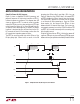
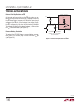
DC/DC Turn-Off Blanking
When the DC/DC converter is turned off, it can take a sig-
nificant amount of time for its output to decay to ground. It
is desirable to wait until the output of the DC/DC converter
is near ground before allowing the user (via PB ) to restart
the converter. This condition guarantees that the µP has
always powered down completely before it is restarted.
Figure 4 shows the µP turning power off. After a low on KILL
releases enable, PB is ignored during the internal 256ms
timer period. This is shown as t
EN/EN, LOCKOUT
in Figure 4.
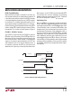
LTC2951-1, LTC2951-2 Versions
The LTC2951-1 (high true EN) and LTC2951-2 (low true
EN) differ only by the polarity of the EN/EN pin. Both ver-
sions allow the user to extend the amount of time that the
PB must be held low in order to begin a valid power-off
sequence. An external capacitor placed on the OFFT pin
adds additional time to the turn-off debounce time. If
no capacitor is placed on the OFFT pin, then the turn-off
debounce time is given by an internally fixed 32ms timer.
Both versions of the LTC2951 provide extendable KILL
turn-off timer, t
KILL, OFF DELAY, ADDITIONAL
, by connecting
an optional external capacitor on the KILLT pin. The default
KILL turn-off delay time is 128ms, t
KILL
,
OFF DELAY
.
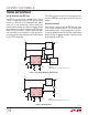
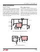
High Voltage Pins
The V
IN
and PB pins can operate at voltages up to 26.4V.
PB can, additionally, operate below ground (–6V) without
latching up the device. PB has an ESD HBM rating of ±10kV.
If the pushbutton switch connected to PB exhibits high
leakage current, then an external pull-up resistor to V
IN
is
recommended. Furthermore, if the pushbutton switch is
physically located far from the LTC2951 PB pin, parasitic
capacitances may couple onto the high impedance PB
input. Additionally, parasitic series inductance may cause
unpredictable ringing at the PB pin. Placing a 5k resistor
from the PB pin to the pushbutton switch would mitigate
parasitic inductance problems. Placing a 0.1µF capacitor
on the PB pin would lessen the impact of parasitic capaci-
tive coupling.
APPLICATIONS INFORMATION
Figure 4. DC/DC Turn-Off Blanking (LTC2951-1)
PB & KILL IGNORED
PB
PB IGNORED
EN
KILL
PB BLANKING
XXX DON’T CARE
256ms
POWER ON
2951 F04
DC/DC
TURNS OFF
t
EN/EN, LOCKOUT
µP SETS
KILL LOW