
Datasheet


LTC2955
15
2955f
V
TH
= 0.8V INPUT
*OPTIONAL
2955 F10
PB
INT
KILL
V
IN
LTC2955TS8-2
R4
100k
1%
GND TMR
C
TMR*
0.033µF
EN
V
OUT
V
OUT
,TRIP POINT = 6V
ON
C4
0.1µF
R1
649k
1%
R9
100k
M1
R5*
100k
C3*
0.1µF
OPTIONAL GLITCH
FILTER CAPACITOR
4.2V
SINGLE CELL
Li-ION BATTERY
+
4.2V
SINGLE CELL
Li-ION BATTERY
+
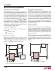
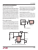
High Voltage PowerPath™ Switching
The high voltage EN open drain output of the LTC2955-2
is designed to switch on/off an external power P-channel
MOSFET. This allows a user to connect/disconnect a power
s u p p l y ( o r b a t t e r y ) t o i t s l o a d b y t o g g l i n g t h e PB pin. Figure 10
shows the LTC2955-2 controlling a two cell Li-Ion battery
application. The KILL pin is connected to the output of the
external MOSFET through a resistive divider. The KIL L pin
serves as a voltage monitor. When V
OUT
drops below 6V,
the EN pin is pulled high (to V
IN
) after 15µs later. R9 slows
down the turning on of M1 so as to limit the inrush current
when M1 turns on to charge up the capacitor at V
OUT
. R5
helps to speed up the turning off of M1 and also to keep
M1 off when the input voltage rise time is fast.
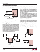
PB Pin in a Noisy Environment
The rugged PB pin is designed to operate in noisy environ-
ments. Transients below ground and above V
IN
(–36V <
V
IN
< 36V) will not damage the rugged PB pin. Additionally,
the PB pin can withstand ESD HBM strikes of up to ±25kV.
However, if the pushbut ton switch is loc ated physically far
from the LTC2955 PB pin, the parasitic capacitance and
parasitic series inductance of the connecting cable or PCB
trace can create problems. The parasitic capacitance can
couple external noise onto the PB input; placing a 0.1µF
capacitor at the pin lessens the impact of this coupling.
The parasitic series inductance may cause unpredictable
ringing at the PB pin; placing a 5.1k resistor from the PB
pin to the pushbutton switch reduces this ringing. Figure 11
shows an example of this RC network at the PB pin.
External Pull-Up Resistor on PB Pin
An internal 900k pull-up resistor on the PB pin makes an
external pull-up resistor unnecessary. Leakage current on
the PB board trace, however, will affect the open circuit
voltage on the PB pin. If the leakage is too large (>1µA),
the PB voltage may fall close to the threshold window. To
APPLICATIONS INFORMATION
Figure 10. PowerPath Control with 6V Undervoltage Detect
Figure 11. Noisy PB Trace
DETAILS OMITTED
FOR CLARITY
PB INT
KILL
V
IN
LTC2955-1
GND TMR
EN
C5
0.1µF
R6
5.1k
TRACE
CAPACITANCE
PARASITICS
TRACE
INDUCTANCE
NOISE
V
IN
2955 F11