
Datasheet


LTC2996
12
2996f
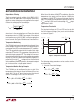
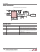
Figure 6. Monitoring Internal Temperature
applicaTions inForMaTion
where η
ACT
denotes the actual ideality factor if an external
sensor is used and T1 and T2 are the desired threshold
temperatures in degrees Kelvin.
2. Choose R
TA
to obtain the desired VTL threshold for
a desired current through the resistive divider
(I
REF
):
R
TA
=
VTL
I
REF
3. Choose R
TB
to obtain the desired VTH threshold:
R
TB
=
VTH – VTL
I
REF
4. Finally R
TC
is determined by:
R
TC
=
1.8V – VTH
I
REF
In the Temperature Monitor example discussed earlier with
thresholds at VTL = 0°C and VTH = 90°C and a desired
reference current of 10μA, the required values for R
TA
,
R
TB
and R
TC
can be calculated as :
R
TA
=
1.093V
10µA
= 109.3K
R
TB
=
1.453V – 1.093V
10µA
= 36K
R
TC
=
1.8V – 1.453V
10µA
= 34.7K
D
+
D
–
1.2V
200k
400k
1.8V
V
CC
V
REF
R
TC
VTH
VTL
V
CC
V
PTAT
OT
UT
3.3V
LTC2996
2996 F06
R
TB
R
TA
GND
–
+
–
+
–
+
OT/UT
PULSE
GENERATOR
UVLO
V
CC
400k
V
CC
400k
T/V