
Datasheet


LTC3114-1
24
Rev. C
For more information www.analog.com
APPLICATIONS INFORMATION
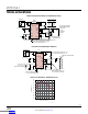
A simplified diagram of the average output current program-
ming circuitry is shown in the Block Diagram. An internal
sense resistor
, R
S
, and low offset amplifier directly measure
current in the V
OUT
path and produce a small fraction of
this current out of the PROG pin. Accordingly, a resistor
and filtering capacitor connected from PROG to ground
produce a voltage proportional to average output current
on PROG. An internal transconductance amplifier compares
the PROG voltage to the fixed 1V internal reference. If the
PROG voltage tries to exceed the 1V reference level, this
amplifier will pull down on VC and take command of the
PWM. As described earlier, VC is the current command
voltage, so limiting VC in this manner will also limit output
current. The resulting average output current is given by
the following equation:
I
OUT(AVG)
≅ 25,000 •
1V
R
PROG
where: R
PROG
= 24.9k to 100k.
The largest recommended PROG pin resistor is 100k. Val-
ues of R
PROG
larger than 100k may latch-off the LTC3114-1
if V
OUT
is forced to less than 2V by an external load. This
is generally not an issue for battery charging applications,
but may prevent the charging of very large capacitors. In
some general purpose power supply applications, this
latch-off behavior may be desirable and in these cases,
values of R
PROG
> 100k are acceptable to use.
The gain of 25,000 is generated internal to the LTC3114-1
and is factory trimmed to provide the best accuracy at
500mA of output current. The accuracy of the programmed
output current is best at the high end of the range as the
residual internal current sense amplifier offset becomes
a smaller percentage of the total current sense signal
amplitude with increasing current. The provided electrical
specifications define the PROG pin current accuracy over
a range of output currents.
Selecting the capacitor, C
PROG
, to put in parallel with
R
PROG
is a trade-off between response time, output cur-
rent ripple and interaction with the normal output voltage
control loop. In general, if speed is not a concern as is the
case for most current sour
cing applications, then C
PROG
should be made at least 3 times higher than the voltage
error amplifier compensation capacitor, C
P1
, described
in the Compensation section of this data sheet. This will
ensure minimal to no interaction when the transition oc-
curs between voltage regulation mode and output current
regulation mode.
In current sourcing applications, the maximum output
compliance voltage of the LTC3114-1 is set by the voltage
error amplifier dividers resistors as it is for standard volt
-
age regulation applications. For LED drivIng applications,
select the V
OUT
divider resistors for a clamping level 1V
to 2V higher than the expected forward voltage drop of
the LED string.
The average output current circuitry can
also be used to monitor, rather than control the output
current. To do this, select an R
PROG
value that will limit
the voltage on the PROG pin to 0.8V or less at the highest
output current expected in the application.
Connect a 20k resistor and 33nF capacitor from PROG to
ground if the function is not going to be used to provide a
higher level of protection against inadvertent short-circuit
conditions on V
OUT
.
Compensation of the Buck-Boost Converter
The LTC3114-1 utilizes average current mode control to
regulate the output voltage. Average current mode control
has two loops that require frequency compensation, the
inner average current loop and the outer voltage loop.
The compensation for the inner average current loop is
fixed within the LTC3114-1 in order to provide the highest
possible bandwidth over the wide operating range of the
LTC3114-1. Therefore, the only control loop that requires
compensation design is the outer voltage loop. As will be
shown, compensation design of the outer loop is similar
to the techniques used in well known peak current mode
control devices.
The LTC3114-1 utilizing average current mode control
can be conceptualized in its simplest form as a voltage-
controlled current source (V
CCS
), driving the output load
formed primarily by R
LOAD
and C
OUT
, as shown in Figure6.
The error amplifier output (VC), provides the command
input to the V
CCS
. The full-scale range of VC is 0.865V
(135mV to 1V). With a full-scale command on VC,
the LTC3114-1 buck-boost converter will generate an
average 1.7A of inductor current (typical) from the con-
Downloaded from Arrow.com.Downloaded from Arrow.com.Downloaded from Arrow.com.Downloaded from Arrow.com.Downloaded from Arrow.com.Downloaded from Arrow.com.Downloaded from Arrow.com.Downloaded from Arrow.com.Downloaded from Arrow.com.Downloaded from Arrow.com.Downloaded from Arrow.com.Downloaded from Arrow.com.Downloaded from Arrow.com.Downloaded from Arrow.com.Downloaded from Arrow.com.Downloaded from Arrow.com.Downloaded from Arrow.com.Downloaded from Arrow.com.Downloaded from Arrow.com.Downloaded from Arrow.com.Downloaded from Arrow.com.Downloaded from Arrow.com.Downloaded from Arrow.com.Downloaded from Arrow.com.