LTC3300-1 High Efficiency Bidirectional Multicell Battery Balancer FEATURES n n n n n n n n n n n DESCRIPTION Bidirectional Synchronous Flyback Balancing of Up to 6 Li-Ion or LiFePO4 Cells in Series Up to 10A Balancing Current (Set by Externals) Integrates Seamlessly with the LTC680x Family of Multicell Battery Stack Monitors Bidirectional Architecture Minimizes Balancing Time and Power Dissipation Up to 92% Charge Transfer Efficiency Stackable Architecture Enables >1000V Systems Uses Simple 2-Winding
LTC3300-1 ABSOLUTE MAXIMUM RATINGS (Note 1) Total Supply Voltage (C6 to V–)..................................36V Input Voltage (Relative to V–) C1 ............................................................ –0.3V to 6V I1P ........................................................ –0.3V to 0.3V I1S, I2S, I3S, I4S, I5S, I6S..................... –0.3V to 0.3V CSBI, SCKI, SDI........................................ –0.3V to 6V CSBO, SCKO, SDOI................................. –0.3V to 36V VREG, SDO...........
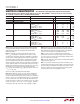
LTC3300-1 ORDER INFORMATION LEAD FREE FINISH TAPE AND REEL PART MARKING* PACKAGE DESCRIPTION TEMPERATURE RANGE LTC3300IUK-1#PBF LTC3300IUK-1#TRPBF LTC3300UK-1 –40°C to 125°C 48-Lead (7mm × 7mm) Plastic QFN LTC3300HUK-1#PBF LTC3300HUK-1#TRPBF LTC3300UK-1 –40°C to 150°C 48-Lead (7mm × 7mm) Plastic QFN LEAD FREE FINISH TRAY PART MARKING* PACKAGE DESCRIPTION TEMPERATURE RANGE LTC3300ILXE-1#PBF LTC3300ILXE-1#PBF LTC3300LXE-1 –40°C to 125°C 48-Lead (7mm × 7mm) Plastic eLQFP LTC3300HLXE-1#PBF LTC3300HLXE-1#PBF LTC
LTC3300-1 ELECTRICAL CHARACTERISTICS The l denotes the specifications which apply over the full operating junction temperature range, otherwise specifications are at TA = 25°C. (Note 2) BOOST+ = 25.2V, C6 = 21.6V, C5 = 18V, C4 = 14.4V, C3 = 10.8V, C2 = 7.2V, C1 = 3.6V, V– = 0V, unless otherwise noted.
LTC3300-1 ELECTRICAL CHARACTERISTICS The l denotes the specifications which apply over the full operating + junction temperature range, otherwise specifications are at TA = 25°C. (Note 2) BOOST = 25.2V, C6 = 21.6V, C5 = 18V, C4 = 14.4V, C3 = 10.8V, C2 = 7.2V, C1 = 3.6V, V– = 0V, unless otherwise noted.
LTC3300-1 ELECTRICAL CHARACTERISTICS The l denotes the specifications which apply over the full operating junction temperature range, otherwise specifications are at TA = 25°C. (Note 2) BOOST+ = 25.2V, C6 = 21.6V, C5 = 18V, C4 = 14.4V, C3 = 10.8V, C2 = 7.2V, C1 = 3.6V, V– = 0V, unless otherwise noted.
LTC3300-1 TYPICAL PERFORMANCE CHARACTERISTICS 1.06 C6 = 21.6V IQ(ACTIVE)/IQ(ACTIVE AT 25°C) 2.05 16 1.95 1.00 14 12 0.98 TYP = 740µA TYP = 560µA TYP = 250µA TYP = 70µA TYP = 60µA TYP = –70µA 0.96 0 0.94 –50 –25 25 50 75 100 125 150 TEMPERATURE (°C) 0 5.2 1.80 –50 –25 5.0 CELL VOLTAGE RISING VREG Load Regulation 4.70 TA = 25°C 4.69 VREG Voltage vs Temperature IVREG = 10mA 4.68 4.9 C6 = 36V 4.7 4.6 CELL VOLTAGE FALLING 4.4 4.8 4.66 C6 = 9V VREG (V) 4.
LTC3300-1 TYPICAL PERFORMANCE CHARACTERISTICS VRTONP, VRTONS vs External Resistance 1.236 TA = 25°C unless otherwise specified. WDT Pin Current vs Temperature 85 TA = 25°C RTONS = 15k BALANCING WDT = 0.5V 1.224 80 VRTONP, VRTONS (V) WDT Pin Current vs RTONS 240 200 1.212 75 SECONDARY OV WDT = 2V 1.188 VRTONS IWDT (µA) IWDT (µA) 160 1.200 70 VRTONP 10 RTONP, RTONS RESISTANCE (kΩ) 65 –50 –25 100 0 VZERO_P, VZERO_S (mV) VPEAK_P, VPEAK_S (mV) 49 8.0 0 SECONDARY –7.
LTC3300-1 TYPICAL PERFORMANCE CHARACTERISTICS 3.00 CSBO Digital Output Current Low vs Temperature 1500 TOS = V– 93 TOS = V– 1400 2.75 IOH1 (µA) IOL1 (µA) 1300 2.50 1200 2.25 1100 2.00 –50 –25 0 25 50 75 100 125 150 TEMPERATURE (°C) 1000 –50 –25 0 25 50 75 100 125 150 TEMPERATURE (°C) Balance Current vs Cell Voltage BALANCE CURRENT (A) 2.6 2.4 DISCHARGE, 12-CELL STACK DISCHARGE, 6-CELL STACK DC2064A DEMO BOARD ICHARGE = IDISCHARGE = 2.5A FOR 12-CELL STACK ONLY 2.3 2.2 2.1 2.
LTC3300-1 PIN FUNCTIONS Note: The convention adopted in this data sheet is to refer to the transformer winding paralleling an individual battery cell as the primary and the transformer winding paralleling multiple series-stacked cells as the secondary, regardless of the direction of energy transfer. CSBI (Pin 16): Chip Select (Active Low) Input. The CSBI pin interfaces to a rail-to-rail output logic gate if VMODE is tied to VREG.
LTC3300-1 PIN FUNCTIONS G1P, G2P, G3P, G4P, G5P, G6P (Pins 23, 26, 29, 32, 35, 38): G1P through G6P are gate driver outputs for driving external NMOS transistors connected in series with the primary windings of transformers connected in parallel with battery cells 1 through 6. SCKO (Pin 44): Serial Clock Output. SCKO is a buffered and one-shotted version of the serial clock input, SCKI, when CSBI is low. SCKO drives the next IC higher in the daisy chain.
LTC3300-1 BLOCK DIAGRAM 48 41 VREG C6 VOLTAGE REGULATOR V– C6 40mA MAX THERMAL SHUTDOWN 4.
LTC3300-1 TIMING DIAGRAM Timing Diagram of the Serial Interface t4 t1 t2 t3 t6 t7 SCKI SDI t5 CSBI t8 SDO 33001 TD 33001fb For more information www.linear.
LTC3300-1 OPERATION Battery Management System (BMS) The LTC3300-1 multicell battery cell balancer is a key component in a high performance battery management system (BMS) for series-connected Li-Ion cells. It is designed to operate in conjunction with a monitor, a charger, and a microprocessor or microcontroller (see Figure 1).
LTC3300-1 OPERATION TOP OF STACK + ICHARGE C6 C5 C4 LTC3300-1 BALANCER C3 C2 V– C1 SERIAL COMMUNICATION + C5 C4 LTC3300-1 C3 BALANCER C2 V– CN + CELL N – 2 + CELL N – 3 + CELL N – 4 + CELL N – 5 C1 CELL N – 6 + CELL N – 7 + C10 C9 C8 C7 C6 LTC6803-1 MONITOR C5 C4 C3 CELL N – 9 + CELL N – 10 + + C6 C5 C4 C3 C2 V– C1 SERIAL COMMUNICATION + + + + + + C6 LTC3300-1 BALANCER V – C5 C4 C3 + + + C2 + C1 + ILOAD C12 C2 V– C1 CELL N – 11 • SERIAL • • COMMUNICATION •
LTC3300-1 OPERATION Synchronous Flyback Balancer charge from the highest voltage cell(s) in the stack to other lower voltage cells in the stack (active balancing). This can be very efficient (in terms of charge recovery) for the case where only a few cells in the overall stack are high, but will be very inefficient (and time consuming) for the case where only a few cells in the overall stack are low.
LTC3300-1 OPERATION Cell Discharging (Synchronous) When discharging is enabled for a given cell, the primary side switch is turned on and current ramps in the primary winding of the transformer until the programmed peak current (IPEAK_PRI) is detected at the In P pin. The primary side switch is then turned off, and the stored energy in the transformer is transferred to the secondary-side cells causing current to flow in the secondary winding of the transformer.
LTC3300-1 OPERATION 6.8Ω 0.1µF – BOOST BOOST+ UP TO • CELL 12 •• C6 10µF 1:1 • 10µH 10µH • G6P + CELL 6 I6P 25mΩ G6S I6S 25mΩ C5 10µF 1:1 • 10µH 10µH • G5P + I5P CELL 5 25mΩ G5S I5S 25mΩ C4 LTC3300-1 • • • • • • C3 C2 10µF 1:1 • 10µH 10µH • G2P CSBO SCKO SDOI CELL 2 25mΩ CSBI SCKI SDI SDO SERIAL COMMUNICATION RELATED PINS + I2P G2S I2S 25mΩ TOS VMODE WDT C1 10µF 1:1 • 10µH 10µH • G1P + I1P CELL 1 25mΩ VREG G1S BOOST I1S 25mΩ CTRL 10µF RTONP RTONS 22.
LTC3300-1 OPERATION Balancing High Voltage Battery Stacks TOP Balancing series connected batteries which contain >>12 cells in series requires interleaving of the transformer secondary connections in order to achieve full stack balancing while limiting the breakdown voltage requirements of the primary- and secondary-side power FETs. Figure 4 shows typical interleaved transformer connections for a multicell battery stack in the generic sense, and Figure 5 for the specific case of an 18-cell stack.
LTC3300-1 OPERATION 0.1µF 6.
LTC3300-1 OPERATION Gate Drivers/Gate Drive Comparators All secondary-side gate drivers (G1S through G6S) are powered from the VREG output, pulling up to 4.8V when on and pulling down to V– when off. All primary-side gate drivers (G1P through G6P) are powered from their respective cell voltage and the next cell voltage higher in the stack (see Table 1).
LTC3300-1 OPERATION Voltage Regulator Thermal Shutdown A linear voltage regulator powered from C6 creates a 4.8V rail at the VREG pin which is used for powering certain internal circuitry of the LTC3300-1 including all 6 secondary gate drivers. The VREG output can also be used for powering external loads, provided that the total DC loading of the regulator does not exceed 40mA at which point current limit is imposed to limit on-chip power dissipation.
LTC3300-1 OPERATION out, externally pulling the WDT pin high will immediately pause balancing, and it will resume where it left off when the pin is released. only restart if an execute command is written. To defeat the watchdog function, simply connect the WDT pin to V–.
LTC3300-1 OPERATION the WDT pin from high voltage. The secondary winding OVP thresholds are given by: VSEC|OVP(RISING) = 1.4V + 1.2V • (RSEC_OVP/RTONS) VSEC|OVP(FALLING) = 1.4V + 1.05V • (RSEC_OVP/RTONS) This comparator will protect the LTC3300-1 application circuit if the secondary winding connection to the battery stack is lost while balancing and the secondary winding voltage is still increasing as a result of that balancing.
LTC3300-1 OPERATION 0.1µF 6.8Ω • • • BOOST– BOOST+ UP TO CELL 12 EACH 1:1 • C6 10µH 10µF • G6P I6P + C5 25mΩ CELL 6 10µH 10µF • G5P I5P + C4 25mΩ CELL 5 10µH 10µF • G4P I4P + LTC3300-1 C3 25mΩ CELL 4 10µH 10µF • G3P I3P + C2 25mΩ CELL 3 10µH 10µF G2P CSBO SCKO SDOI I2P + CSBI SCKI SDI SDO SERIAL COMMUNICATION RELATED PINS • C1 25mΩ CELL 2 10µH 10µF TOS VMODE WDT G1P VREG G1S • I1P 25mΩ I1S G2S-G6S I2S-I6S CTRL V– RTONP RTONS BOOST 10µF 22.
LTC3300-1 OPERATION Transmission Format (Write) CSBI SCKI SDI MSB (CMD) LSB (CMD) MSB (DATA) LSB (DATA) Transmission Format (Read) CSBI SCKI SDI MSB (CMD) LSB (CMD) SDO MSB (DATA) LSB (DATA) 33001 F08 Figure 8 See Figure 9. Since CSBO, SCKO and SDOI voltages are close to the V– of the high side device, the V– of the high side device must be at least 5V higher than that of the low side device to guarantee current flows of the current mode interface.
LTC3300-1 OPERATION pin must be pulled high (tied to VREG). The other devices in the daisy chain must have this pin pulled low (tied to V–) to designate current mode communication. To designate the top-of-stack device, the TOS pin on the top device of a daisy chain must be tied high. The other devices in the stack must have TOS tied low. See the application on the last page of this data sheet. Command Byte All communication to the LTC3300-1 takes place with CSBI logic low.
LTC3300-1 OPERATION The first 12 bits of the 16-bit balance command are used to indicate which balancer (or balancers) is active and in which direction (charge or discharge). Each of the 6 cell balancers is controlled by 2 bits of this data per Table 5. The balancing algorithm for a given cell is: Charge Cell n: Ramp up to IPEAK in secondary winding, ramp down to IZERO in primary winding. Repeat. Discharge Cell n (Synchronous): Ramp up to Ipeak in primary winding, ramp down to IZERO in secondary winding.
LTC3300-1 OPERATION Read Balance Status If the command bits program Read Balance Status, successive 16-bit status data (12 bits of data plus associated 4-bit CRC) are shifted out MSB first per Table 6. Similar to a Readback Balance Command, the last 4 bits in each 16-bit balance status are used for error detection. The first 12 bits of the status are input to a cyclic redundancy check (CRC) block employing the same characteristic polynomial used for write commands.
LTC3300-1 APPLICATIONS INFORMATION External Sense Resistor Selection LTC3300-1 The external current sense resistors for both primary and secondary windings set the peak balancing current according to the following formulas: RSENSE|PRIMARY = G1P/GnP/G1S/GnS 20µA I1P/InP/I1S/InS C V–/Cn – 1/V–/V– 50mV n = 2 TO 6 IPEAK _PRI RSENSE|SECONDARY = R RSNS 33001 F10 Figure 10.
LTC3300-1 APPLICATIONS INFORMATION External FET Selection In addition to being rated to handle the peak balancing current, external NMOS transistors for both primary and secondary windings must be rated with a drain-to-source breakdown such that for the primary MOSFET: VSTACK + VDIODE T ⎛ S⎞ V = VCELL ⎜ 1+ ⎟ + DIODE ⎝ T⎠ T VDS(BREAKDOWN)|MIN > VCELL + See Table 8 for a list of transformers that are recommended for use with the LTC3300-1.
LTC3300-1 APPLICATIONS INFORMATION Boosted Gate Drive Component Selection (BOOST = VREG) The external boost capacitor connected from BOOST+ to BOOST– supplies the gate drive voltage required for turning on the external NMOS connected to G6P. This capacitor is charged through the external Schottky diode from C6 to BOOST+ when the NMOS is off (G6P = BOOST– = C5).
LTC3300-1 APPLICATIONS INFORMATION • • • • • • C6 + C5 C4 LTC3300-1 C3 C2 V– CELL n + 4 + C6 + C5 CELL n + 3 C4 + LTC3300-1 CELL n + 2 C3 + CELL n + 1 • • • CELL n + 3 + C6 CELL n C1 V– C4 + LTC3300-1 CELL n + 1 + CELL n + 1 + CELL n CELL n C2 C1 V– • • • (11a) Sub-Stack Using Only 5 Cells CELL n + 2 C3 + • • • C5 CELL n + 2 C2 + + C1 • • • (11b) Sub-Stack Using Only 4 Cells 33001 F11 (11c) Sub-Stack Using Only 3 Cells Figure 11.
LTC3300-1 APPLICATIONS INFORMATION Fault Protection Care should always be taken when using high energy sources such as batteries. There are numerous ways that systems can be misconfigured when considering the assembly and service procedures that might affect a battery system during its useful lifespan. Table 9 shows the various situations that should be considered when planning protection circuitry.
LTC3300-1 APPLICATIONS INFORMATION Battery Interconnection Integrity The FMEA scenarios involving a break in the stack of battery cells are potentially the most damaging. In the case where the battery stack has a discontinuity between groupings of cells balanced by LTC3300-1 ICs, any load will force a large reverse potential on the daisy-chain connection. This situation might occur in a modular battery system during initial installation or a service procedure.
LTC3300-1 APPLICATIONS INFORMATION VREG WDT SDO LTC3300-1 SDI SCKI 45 44 43 40 CSBO CSBI TOS SCKO VMODE SDOI BOOST BOOST+ CTRL RTONP 41 39 38 37 36 35 34 33 32 31 30 29 28 27 26 25 24 23 22 BOOST– RTONS 48 20 19 18 17 16 47 46 42 15 14 13 C6 G6P G6S I6P I6S 1 2 C5 G5P G5S I5P I5S C4 3 4 ZCLAMP G4P G4S ZCLAMP I4P I4S 5 6 C3 G3S G3P ZCLAMP I3P C2 I3S 7 8 ZCLAMP G2P G2S I2P I2S 9 10 C1 G1P G1S I1P I1S 11 12 4Ω EXPOSED PAD 49 V– 21 33001 F14 Figure 14
LTC3300-1 APPLICATIONS INFORMATION Analysis of Stack Terminal Currents in Shutdown As given in the Electrical Characteristics table, the quiescent current of the LTC3300-1 when not balancing is 16μA at the C6 pin and zero at the C1 through C5 pins. All of this 16μA shows up at the V– pin of the LTC3300-1. In addition, the SPI port when not communicating (i.e., CSBI = 1) contributes an additional 2.5μA per high side line (CSBO/SCKO/SDOI), or 7.
LTC3300-1 APPLICATIONS INFORMATION How to Calculate the CRC One simple method of computing an n-bit CRC is to perform arithmetic modulo-2 division of the n+1 bit characteristic polynomial into the m bit message appended with n zeros (m+n bits). Arithmetic modulo-2 division resembles normal long division absent borrows and carries.
LTC3300-1 APPLICATIONS INFORMATION “Ø” “Ø” D6B D5B CRC [3] D3B D1B CRC [3] D2A D5A CRC [2] D3A D1A CRC [2] D4B CRC [1] D2B CRC [1] D4A D6A “Ø” CRC [0] “Ø” CRC [0] 33001 F17 Figure 17. Combinational Logic Circuit Implementation of The CRC Calculator Serial Communication Using the LTC6803 and LTC6804 The LTC3300-1 is compatible with and convenient to use with all LTC monitor chips, such as the LTC6803 and LTC6804.
LTC3300-1 APPLICATIONS INFORMATION PCB Layout Considerations G6S—PIN 1 I6S G5S I5S G4S I4S G3S I3S G2S I2S G1S I1S LTC3300-1 (EXPOSED PAD = 0V) RTONS RTONP CTRL CSBI SCKI SDI SDO WDT V– I1P G1P C1 0V TO 4.8V 0V 0V TO 4.8V 0V 0V TO 4.8V 0V 0V TO 4.8V 0V 0V TO 4.8V 0V 0V TO 4.8V 0V VREG 4.8V TOS 0V/4.8V VMODE 0V/4.8V CSBO 24.5V SCKO 24.5V SDOI 24.5V BOOST 0V/4.8V BOOST– 21V TO 25.2V BOOST+ 25.2V TO 29.4V C6 25.2V G6P 21V TO 29.
LTC3300-1 TYPICAL APPLICATIONS 6.8Ω 0.
LTC3300-1 TYPICAL APPLICATIONS TOP OF BATTERY STACK NC NC NC NC D9 D8 C6 SDOI C5 SCKO C4 CSBO C3 LTC3300-1 C2 C1 CSBI VREG SCKI TOS SDI VMODE SDO V– + + + + CVREG4 + + D7 + C6 NC D6 D5 SDOI C5 SCKO C4 CSBO C3 LTC3300-1 C2 C1 CSBI VREG SCKI TOS SDI VMODE SDO – V + + + CVREG3 + D4 + C6 NC D3 D2 + SDOI C5 SCKO C4 CSBO C3 LTC3300-1 C2 C1 CSBI VREG SCKI TOS SDI VMODE SDO – V + + + CVREG2 + + D1 + DIGITAL ISOLATOR 3V V1+ V2+ CS MPU CLK VREG1 OR VREG5 C6 SDOI C5 SCKO C4 CSBO C3 LTC
LTC3300-1 PACKAGE DESCRIPTION Please refer to http://www.linear.com/designtools/packaging/ for the most recent package drawings. UK Package 48-Lead Plastic QFN (7mm × 7mm) (Reference LTC DWG # 05-08-1704 Rev C) 0.70 ±0.05 5.15 ±0.05 5.50 REF 6.10 ±0.05 7.50 ±0.05 (4 SIDES) 5.15 ±0.05 PACKAGE OUTLINE 0.25 ±0.05 0.50 BSC RECOMMENDED SOLDER PAD PITCH AND DIMENSIONS APPLY SOLDER MASK TO AREAS THAT ARE NOT SOLDERED 7.00 ±0.10 (4 SIDES) 0.75 ±0.05 R = 0.10 TYP R = 0.115 TYP 47 48 0.40 ±0.
LTC3300-1 PACKAGE DESCRIPTION Please refer to http://www.linear.com/designtools/packaging/ for the most recent package drawings. LXE Package 48-Lead Plastic Exposed Pad LQFP (7mm × 7mm) (Reference LTC DWG # 05-08-1832 Rev B) 7.15 – 7.25 5.50 REF 1 48 37 36 0.50 BSC C0.30 5.50 REF 7.15 – 7.25 0.20 – 0.30 3.60 ± 0.05 3.60 ± 0.05 12 13 PACKAGE OUTLINE 24 25 1.30 MIN RECOMMENDED SOLDER PAD LAYOUT APPLY SOLDER MASK TO AREAS THAT ARE NOT SOLDERED 9.00 BSC 7.00 BSC 48 3.60 ± 0.
LTC3300-1 REVISION HISTORY REV DATE DESCRIPTION PAGE NUMBER A 6/13 Added Tray ordering option for LXE package 3 Modified transformer part number in Table 8 31 B 12/13 Add new bullet Integrates Seamlessly with the LTC680x Family of Multicell Battery Stack Monitors 1 Change part number XF0036-EP135 to XF0036-EP13S 31 33001fb Information furnished by Linear Technology Corporation is believed to be accurate and reliable. However, no responsibility is assumed for its use.
LTC3300-1 TYPICAL APPLICATIONS LTC3300-1/LTC6804-1 Serial Communication Connections DATA 12-CELL MODULE 2 LTC3300-1 ISO OUT 9 CELLS 3 LTC3300-1 SCKI SDI SDO CSBI LTC6804-1 GPIO5 GPIO4 ISO IN GPIO3 12-CELL MODULE 1 LTC3300-1 ISO OUT 12 CELLS 3 LTC3300-1 SCKI SDI SDO CSBI LTC6820 isoSPI LTC6804-1 GPIO5 GPIO4 ISO IN ISO SPI 4 GPIO3 33001 TA02 RELATED PARTS PART NUMBER DESCRIPTION COMMENTS LTC6801 Independent Multicell Battery Stack Monitor Monitors Up to 12 Series-Connected Battery Cells fo