
Datasheet


LTC3350
18
3350fc
For more information www.linear.com/LTC3350
operaTion
When the difference between any two capacitor volt-
ages exceeds
about 10mV, the capacitor with the largest
voltage is discharged with a resistive balancer at about
10mA
until all capacitor voltages are within 10mV. The
balancers are disabled in backup mode.
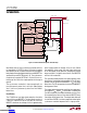
Capacitor Shunt Regulators
In addition to balancing, there is a need to protect each
capacitor from overvoltage during charging. The capacitors
in the stack will not have exactly the same capacitance due
to manufacturing tolerances or uneven aging. This will
cause the capacitor voltages to increase at different rates
with the same charge current. If this mismatch is severe
enough or if the capacitors are being charged to near their
maximum voltage, it becomes necessary to limit the volt
-
age increase on some capacitors while still charging the
other capacitors. Up to 500mA of current may be shunted
around a capacitor whose voltage is approaching the pro
-
grammable shunt voltage. This shunt current reduces the
charge rate of that capacitor relative to the other capacitors.
If a capacitor continues to approach its shunt voltage, the
charge current is reduced. This protects the capacitor
from overvoltage while still charging the other capacitors,
although at a reduced rate of charge.
The shunt voltage is
programmable
in the vshunt register. Shunt voltages up
to 3.6V may be programmed in 183.5µV increments. The
shunt regulators can be disabled by programming vshunt
to zero (0x0000). The default value is 0x3999, resulting
in a shunt voltage of 2.7V.
I
2
C/SMBus and SMBALERT
The LTC3350 contains an I
2
C/SMBus port. This port allows
communication with the LTC3350 for configuration and
reading back telemetry data. The port supports two SMBus
formats, read word and write word. Refer to the SMBus
specification for details of these formats. The registers
accessible via this port are organized on an 8-bit address
bus and each register is 16 bits wide. The “command code”
(or sub-address) of the SMBus read/write word formats is
the 8-bit address of each of these registers. The address
of the LTC3350 is 0b0001001.
The SMBALERT pin is asserted (pulled low) whenever an
enabled limit is exceeded or when an enabled status event
happens (see Limit Check and Alarms and Monitor Status
Register). The LTC3350 will deassert the SMBALERT
pin only after responding to an SMBus alert response
address (ARA), an
SMBus protocol used to respond to a
SMBALERT. The host will read from the ARA (0b0001100)
and
each part asserting SMBALERT will begin to respond
with its address. The responding parts arbitrate in such a
way that only the part with the lowest address responds.
Only when a part has responded with its address does it
release the SMBALERT signal. If multiple parts are as
-
serting the SMBALERT signal then multiple reads from
the ARA are needed. For more information refer to the
SMBus specification.
Details on the registers accessible through this interface
are available in the Register Map and Register Descriptions
sections of this data sheet.
Analog-to-Digital Converter
The LTC3350 has an integrated 14-bit sigma-delta analog-
to-digital converter (ADC). This converter is automatically
multiplexed between all of the measured channels and
its results are stored in registers accessible via the I
2
C/
SMBus port. There are 11 channels measured by the ADC,
each of which takes approximately 1.6ms to measure. In
addition to providing status information about the system
voltages and currents, some of these measurements are
used by the LTC3350 to balance, protect, and measure
the capacitors in the stack.
The result of the analog-to-digital conversion is stored in
a 16-bit register as
a signed, two’s complement number.
The
lower two bits of this number are sub-bits. These bits
are ADC outputs which are too noisy to be reliably used
on any single conversion, however, they may be included
if multiple samples are averaged.
The measurements from the ADC are directly stored in the
meas_vcap1, meas_vcap2, meas_vcap3, meas_vcap4,
meas_gpi, meas_vin, meas_vcap, meas_vout, meas_iin,
meas_ichg and meas_dtemp registers.
Capacitance and ESR Measurement
The LTC3350 has the ability to measure the capacitance
and equivalent series resistance (ESR) of its supercapacitor
Downloaded from Arrow.com.Downloaded from Arrow.com.Downloaded from Arrow.com.Downloaded from Arrow.com.Downloaded from Arrow.com.Downloaded from Arrow.com.Downloaded from Arrow.com.Downloaded from Arrow.com.Downloaded from Arrow.com.Downloaded from Arrow.com.Downloaded from Arrow.com.Downloaded from Arrow.com.Downloaded from Arrow.com.Downloaded from Arrow.com.Downloaded from Arrow.com.Downloaded from Arrow.com.Downloaded from Arrow.com.Downloaded from Arrow.com.