
Datasheet


LTC3411A
13
3411afc
For more information www.linear.com/LTC3411A
In most applications, the input capacitor is merely required
to supply high frequency bypassing, since the impedance
to the supply is very low. A 10µF ceramic capacitor is
usually enough for these conditions.
Setting the Output Voltage
The LTC3411A develops a 0.8V reference voltage between
the feedback pin, V
FB
, and the signal ground as shown in
Figure 4. The output voltage is set by a resistive divider
according to the following formula:
V
OUT
≈ 0.8V 1+
R2
R1
⎛
⎝
⎜
⎞
⎠
⎟
Keeping the current small (<5µA) in these resistors maxi-
mizes efficiency, but making them too small may allow
stray capacitance to cause noise problems and reduce the
phase margin of the error amp loop.
To
improve the frequency response, a feed-forward capaci
-
tor C
F
may also be used. Great care should be taken to
route the V
FB
line away from noise sources, such as the
inductor or the SW line.
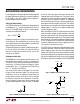
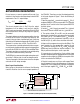
Shutdown and Soft-Start
The SHDN/R
T
pin is a dual purpose pin that sets the oscil-
lator frequency and provides a means to shut down the
LTC3411A. This pin can be inter
faced with control logic in
several ways, as shown in Figure 2 and Figure 3. In both
configurations, Run = “0” shuts down the LTC3411A and
Run = “1” activates the LTC3411A.
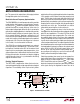
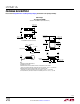
Care must be taken when using Figure 3 to shut down
the part in force continuous mode. The pull up resistor
should be as small as the application would allow and
the pull down transistor should be as small as possible
to minimize its parasitic drain capacitance. If possible,
always shut down the part while in pulse skipping mode
or Burst Mode operation. Figure 4 shows an example
of how to switch from force continuous mode to pulse
skipping mode when RUN goes low. The parasitic drain
capacitance of a large transistor coupled with a large pull
up resistor results in large RC constants. As RUN goes
low, the transistor drain charges up slowly, gradually de
-
creasing the oscillator frequency of the part. This leads to
large inductor current ripples translating into large output
voltage ripples. In some cases, the output voltage could
rise up to dangerous levels.
When activating the L
TC3411A, an internal soft-start slowly
ramps the output voltage up until regulation. Soft-start
prevents surge currents from V
IN
by gradually ramping
the output voltage up during start-up. The output will ramp
from zero to full scale over a time period of approximately
0.7ms. This prevents the LTC3411A from having to quickly
charge the output capacitor and thus supplying an exces
-
sive amount of instantaneous current.
The
L
TC3411A can start into a back-biased output in forced
continuous operation. When the output is pre-biased at
either a higher or lower value than the regulated output
voltage, the LTC3411A will sink or source current as needed
to bring the output back into regulation. However, during
soft-start the regulator will always start in pulse skipping
mode ignoring the mode selected with the SYNC/MODE
applicaTions inForMaTion
Figure 2. SHDN/R
T
Pin Activated with a Logic Input
Figure 4. Automatic Mode Change Circuit
3411A F02
RUN
R
T
SHDN/R
T
Figure 3. SHDN/R
T
Pin Activated with a Switch
3411A F03
RUN
R
T
SHDN/R
T
100k
SV
IN
3411A F04
R
T
SHDN/R
T
1M
SV
IN
100k
100k
SYNC/MODE
0V
3V
ONOFF