
Datasheet

LTC3442
11
3442fb
For more information www.linear.com/LTC3442
OPERATION
For automatic operation, a filter capacitor should also
be connected from BURST to ground to prevent ripple
on BURST from causing the IC to oscillate in and out of
Burst Mode operation. The equation for the minimum
capacitor value is:
C
BURST(MIN)
≥
C
OUT
• V
OUT
60,000
where C
BURST(MIN)
and C
OUT
are in µF.
In the event that a load transient causes the feedback pin
to drop by more than 4% from the regulation value while
in Burst Mode operation, the IC will immediately switch
to fixed frequency mode and an internal pull-up will be
momentarily applied to BURST, rapidly charging the
BURST cap. This prevents the IC from immediately re-
entering Burst Mode operation once the output achieves
regulation.
Manual Burst Mode Operation
For manual control of Burst Mode operation, the RC
network connected to BURST can be eliminated. To force
fixed frequency mode, BURST should be connected to
V
OUT
. To force Burst Mode operation, BURST should be
grounded. When commanding Burst Mode operation
manually, the circuit connected to BURST should be able
to sink up to
2mA.
For optimum transient response with large dynamic loads,
the operating mode should be controlled manually by the
host. By commanding fixed frequency operation prior to
a sudden increase in load, output voltage droop can be
minimized. Note that if the load current applied during
forced Burst Mode operation (BURST pin is grounded)
exceeds the current that can be supplied, the output
voltage will start to droop
and the IC will automati-
cally come out of Burst Mode operation and enter fixed
frequency mode, raising V
OUT
. Once regulation is achieved,
the IC will then enter Burst Mode operation once again,
and the cycle will repeat, resulting in about 4% output
ripple. Note that Burst Mode operation is inhibited during
soft-start.
Burst Mode Operation to Fixed Frequency Transient
Response
In Burst Mode operation,
the compensation network is
not used and V
C
is disconnected from the error amplifier.
During long periods of Burst mode operation, leakage
currents in the external components or on the PC board
could cause the compensation capacitor to charge (or
discharge), which could result in a large output transient
when returning to fixed frequency mode of operation, even
at the same load current. To prevent this, the
LTC3442
incorporates an active clamp circuit that holds the voltage
on V
C
at an optimal voltage during Burst Mode operation.
This minimizes any output transient when returning to
fixed frequency mode operation. For optimum transient
response, Type 3 compensation is also recommended
to broad band the control loop and roll off past the two
pole response of the output LC filter. (See Closing the
Feedback Loop.)
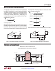
Soft
-Start
The soft-start function is combined with shutdown. When
the SHDN/SS pin is brought above 0.7V typical, the IC
is enabled but the EA duty cycle is clamped from V
C
. A
detailed diagram of this function is shown in Figure 5. The
components R
SS
and C
SS
provide a slow ramping voltage
on SHDN/SS to provide a soft-start function. To ensure
that V
C
is not being clamped, SHDN/SS must be raised
above 2.4V. To enable Burst Mode operation, SHDN/SS
must be raised to within 0.5V of V
IN
.