
Datasheet

LTC3442
13
3442fb
For more information www.linear.com/LTC3442
APPLICATIONS INFORMATION
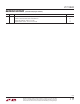
Table 1. Inductor Vendor Information
SUPPLIER PHONE FAX WEB SITE
Coilcraft (847) 639-6400 (847) 639-1469 www.coilcraft.com
CoEv Magnetics (800) 227-7040 (650) 361-2508 www.circuitprotection.com/magnetics.asp
Murata (814) 237-1431
(800) 831-9172
(814) 238-0490 www.murata.com
Sumida USA: (847) 956-0666
Japan: 81(3) 3607-5111
USA: (847) 956-0702
Japan: 81(3) 3607-5144
www.sumida.com
TDK (847) 803-6100 (847) 803-6296 www.component.tdk.com
TOKO (847) 297-0070 (847) 699-7864 www.tokoam.com
For high efficiency, choose a ferrite inductor with a high
frequency core material to reduce core loses. The induc-
tor should have low ESR (equivalent
series resistance) to
reduce the I
2
R losses, and must be able to handle the peak
inductor current without saturating. Molded chokes or chip
inductors usually do not have enough core to support the
peak inductor currents in the 1A to 2A region. To minimize
radiated noise, use a shielded inductor. See Table 1 for a
suggested list of inductor suppliers.
Output Capacitor Selection
The bulk value of
the output filter capacitor is set to reduce
the ripple due to charge into the capacitor each cycle. The
steady-state ripple due to charge is given by:
% RIPPLE_BOOST=
I
OUT(MAX)
• V
OUT
– V
IN(MIN)
( )
• 100
C
OUT
• V
OUT
2
• f
%
% RIPPLE_BUCK =
I
OUT(MAX)
• V
IN(MAX)
– V
OUT
( )
• 100
C
OUT
• V
IN(MAX)
• V
OUT
• f
%
where C
OUT
= output filter capacitor in Farads and
f = switching frequency in Hz.
The output capacitance is usually many times larger than
the minimum value in order to handle the transient response
requirements of the converter. For a rule of thumb, the ratio
of the operating frequency to the unity-gain bandwidth of
the converter is the amount the output capacitance will
have to increase from
the above calculations in order to
maintain the desired transient response.
The other component of ripple is due to the ESR (equiva-
lent series resistance) of the output capacitor. Low ESR
capacitors should be used to minimize output voltage
ripple. For surface mount applications, Taiyo Yuden or
TDK ceramic capacitors, AVX TPS series tantalum capaci-
tors or Sanyo POSCAP are recommended. See Table 2 for
contact information.
Input
Capacitor Selection
Since V
IN
is the supply voltage for the IC, as well as the input
to the power stage of the converter, it is recommended to
place at least a 4.7µF, low ESR ceramic bypass capacitor
close to the V
IN
and SGND pins. It is also important to
minimize any stray resistance from the converter to the
battery or other power source.
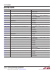
Table 2. Capacitor Vendor Information
SUPPLIER PHONE FAX WEB SITE
AVX (803) 448-9411 (803) 448-1943 www.avxcorp.com
Murata (814) 237-1431
(800) 831-9172
(814) 238-0490 www.murata.com
Sanyo (619) 661-6322 (619) 661-1055 www.sanyovideo.com
Taiyo Yuden (408) 573-4150 (408) 573-4159 www.t-yuden.com
TDK (847) 803-6100 (847) 803-6296 www.component.tdk.com