
Datasheet


LTC3612
14
3612fb
For more information www.linear.com/LTC3612
APPLICATIONS INFORMATION
If the output voltage drops below 50% of its nominal value,
the clamp voltage at ITH pin is lowered causing the maxi-
mum peak inductor current to decrease gradually with the
output voltage. When the output voltage reaches 0V the
clamp voltage at the ITH pin drops to 40% of the clamp
voltage during normal operation. The short-cir
cuit peak
inductor current is determined by the minimum on-time
of the L
TC3612, the input voltage and the inductor value.
This foldback behavior helps in limiting the peak inductor
current when the output is shorted to ground. It is disabled
during internal or external soft-start and tracking up/down
operation (see the Applications Information section).
A secondary limit is also imposed on the valley inductor
current. If the inductor current measured through the
bottom MOSFET increases beyond 6A typical, the top
power MOSFET will be held off and switching cycles will
be skipped until the inductor current is reduced.
OPERATION
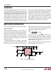
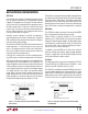
The basic LTC3612 application circuit is shown in Figure 1.
Operating Frequency
Selection of the operating frequency is a trade-off between
efficiency and component size. High frequency operation
allows the use of smaller inductor and capacitor values.
Operation at lower frequencies improves efficiency by
reducing internal gate charge losses but requires larger
inductance values and/or capacitance to maintain low
output ripple voltage.
The operating frequency of the LTC3612 is determined
by an external resistor that is connected between the RT/
SYNC pin and ground. The value of the resistor sets the
RUN
TRACK/SS
RT/SYNC
PGOOD
ITH
SGND
PGND
V
IN
2.25V TO 5.5V
PV
IN_DRV
DDR
SV
IN
LTC3612 SW
PV
IN
C
IN1
22µF
C
C
470pF
C
SS
22nF
L1
470nH
R1
392k
R2
196k
3612 F01
C
IN2
22µF
MODE V
FB
C
OUT1
47µF
C
OUT2
22µF
V
OUT
1.8V
3A
R
C
15k
R
T
130k
R
SS
2M
C
C1
10pF
(OPT)
Figure 1. 1.8V, 3A Step-Down Regulator
ramp current that is used to charge and discharge an
internal timing capacitor within the oscillator and can be
calculated by using the following equation:
R
T
=
3.82•10
11
Hz
f
OSC
Hz
( )
Ω –16kΩ
Although frequencies as high as 4MHz are possible, the
minimum on-time of the LTC3612 imposes a minimum
limit on the operating duty cycle. The minimum on-time
is typically 60ns; therefore, the minimum duty cycle is
equal to 100 • 60ns • f
OSC
(Hz)%.
Tying the RT/SYNC pin to SV
IN
sets the default internal
operating frequency to 2.25MHz ±20%.