
Datasheet


15
LTC3718
3718fa
persists until the RUN/SS pin drops to 3.5V, then the con-
troller turns off both power MOSFETs, shutting down the
converter permanently. The RUN/SS pin must be actively
pulled down to ground in order to restart operation.
The overcurrent protection timer requires that the soft-
start timing capacitor C
SS
be made large enough to guar-
antee that the output is in regulation by the time C
SS
has
reached the 4V threshold. In general, this will depend upon
the size of the output capacitance, output voltage and load
current characteristic. A minimum soft-start capacitor can
be estimated from:
C
SS
> C
OUT
V
OUT
R
SENSE
(10
–4
[F/V s])
Generally 0.1µF is more than sufficient.
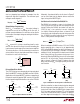
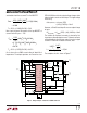
Overcurrent latchoff operation is not always needed or
desired. The feature can be overridden by adding a pull-
up current greater than 5µA to the RUN/SS pin. The
additional current prevents the discharge of C
SS
during a
fault and also shortens the soft-start period. Using a
resistor to V
IN
as shown in Figure 6a is simple, but slightly
increases shutdown current. Connecting a resistor to
INTV
CC
as shown in Figure 6b eliminates the additional
shutdown current, but requires a diode to isolate C
SS
. Any
pull-up network must be able to pull RUN/SS above the
4.2V maximum threshold of the latchoff circuit and over-
come the 4µA maximum discharge current.
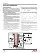
INTV
CC
Supply
The 5V supply that powers the drivers and internal cir-
cuitry within the LTC3718 can be supplied by either an
internal P-channel low dropout regulator if V
IN
is greater
than 5V or the internal boost regulator if V
IN
is less than 5V.
The INTV
CC
pin can supply up to 50mA RMS and must be
bypassed to ground with a minimum of 4.7µF tantalum or
other low ESR capacitor. Good bypassing is necessary to
supply the high transient currents required by the MOSFET
gate drivers. Applications using large MOSFETs with a
high input voltage and high frequency of operation may
cause the LTC3718 to exceed its maximum junction tem-
perature rating or RMS current rating. In continuous mode
operation, this current is I
GATECHG
= f(Q
g(TOP)
+ Q
g(BOT)
).
The junction temperature can be estimated from the
equations given in Note 2 of the Electrical Characteristics.
Inductor Selection for Boost Converter
For the boost converter, the inductance should be 4.7µH
for input voltages less then 3.3V and 10µH for inputs
above 3.3V. The inductor should have a saturation current
rating of approximately 0.5A or greater. A guide for select-
ing an inductor for the boost converter is to choose a ripple
current that is 40% of the current supplied by the boost
converter. To ensure that the ripple current doesn’t exceed
a specified amount, the inductance can be chosen accord-
ing to the following equation:
L
V
V
V
If
IN MIN
IN MAX
OUT BOOST
=
∆
2
2
1
()
()
()
–
•
Diode D3 Selection
A Schottky diode is recommended for use in the boost
converter section. The Motorola MBR0520 is a very good
choice.
Boost Converter Output Capacitor
Because the LTC3718’s boost converter is internally com-
pensated, loop stability must be carefully considered when
choosing its output capacitor. Small, low cost tantalum
capacitors have some ESR, which aids stability. However,
ceramic capacitors are becoming more popular, having
attractive characteristics such as near-zero ESR, small size
and reasonable cost. Simply replacing a tantalum output
capacitor with a ceramic unit will decrease the phase margin,
in some cases to unacceptable levels. With the addition of
a phase-lead capacitor and isolating resistor, the boost
converter portion of the LTC3718 can be used success-
fully with ceramic output capacitors.
Efficiency Considerations
The percent efficiency of a switching regulator is equal to
the output power divided by the input power times 100%.
It is often useful to analyze individual losses to determine
what is limiting the efficiency and which change would
produce the most improvement. Although all dissipative
elements in the circuit produce losses, four main sources
account for most of the losses in LTC3718 circuits:
APPLICATIO S I FOR ATIO
WUUU