
Datasheet


LTC3728L/LTC3728LX
19
3728lxff
applicaTions inForMaTion
current ratings are often based on only 2000 hours of life.
This makes it advisable to further derate the capacitor, or
to choose a capacitor rated at a higher temperature than
required. Several capacitors may also be paralleled to meet
size or height requirements in the design. Always consult
the manufacturer if there is any question.
The benefit of the LTC3728L/LTC3728LX multiphase clock-
ing can be calculated by using the equation above for the
higher power controller and then calculating the loss that
would have resulted if both controller channels switched
on at the same time. The total RMS power lost is lower
when both controllers are operating due to the interleav-
ing of current pulses through the input capacitor’s ESR.
This is why the input capacitor’s requirement calculated
in the previous equation for the worst-case controller is
adequate for the dual controller design. Remember that
input protection fuse resistance, battery resistance and
PC board trace resistance losses are also reduced due to
the reduced peak currents in a multiphase system.
The
overall benefit of a multiphase design will only be fully
realized when the source impedance of the power supply/
battery is included in the efficiency testing.
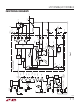
The drains of
the two top MOSFETs should be placed within 1cm of each
other and share a common C
IN
(s). Separating the drains
and C
IN
may produce undesirable voltage and current
resonances at V
IN
.
The selection of C
OUT
is driven by the required effective
series resistance (ESR). Typically once the ESR require-
ment is satisfied the capacitance is adequate for filtering.
The output ripple (ΔV
OUT
) is determined by:
∆V
OUT
≈ ∆I
L
ESR +
1
8fC
OUT
Where f = operating frequency, C
OUT
= output capacitance,
and ΔI
L
= ripple current in the inductor. The output ripple
is highest at maximum input voltage since ΔI
L
increases
with input voltage. With ΔI
L
= 0.3I
OUT(MAX)
the output
ripple will typically be less than 50mV at the maximum
V
IN
assuming:
C
OUT
Recommended ESR < 2 R
SENSE
and C
OUT
> 1/(8fR
SENSE
)
The first condition relates to the ripple current into the ESR
of the output capacitance while the second term guarantees
that the output capacitance does not significantly discharge
during the operating frequency period due to ripple current.
The choice of using smaller output capacitance increases
the ripple voltage due to the discharging term but can be
compensated for by using capacitors of very low ESR to
maintain the ripple voltage at or below 50mV. The I
TH
pin
OPTI-LOOP compensation components can be optimized
to provide stable, high performance transient response
regardless of the output capacitors selected.
Manufacturers such as Nichicon, United Chemi-Con and
Sanyo can be considered for high performance through-
hole capacitors. The OS-CON semiconductor dielectric
capacitor available from Sanyo has the lowest (ESR)
(size) product of any aluminum electrolytic at a somewhat
higher price. An additional ceramic capacitor in parallel
with OS-CON capacitors is recommended to reduce the
inductance effects.
In surface mount applications, multiple capacitors may
need to be used in parallel to meet ESR, RMS cur-
rent handling and load step requirements. Aluminum
electrolytic, dry tantalum and special polymer capaci-
tors are available in surface mount packages. Special
polymer surface mount capacitors offer very low ESR
but have lower storage capacity per unit volume than
other capacitor types. These capacitors offer a very
cost-effective output capacitor solution and are an ideal
choice when combined with a controller having high
loop bandwidth. Tantalum capacitors offer the highest
capacitance density and are often used as output capaci-
tors for switching regulators having controlled soft-start.
Several excellent surge-tested choices are the AVX TPS,
AVX TPSV or the KEMET T510 series of surface mount
tantalums, available in case heights ranging from 2mm
to 4mm. Aluminum electrolytic capacitors can be used
in cost-driven applications providing that consideration
is given to ripple current ratings, temperature and long
term reliability. A typical application will require several
to many aluminum electrolytic capacitors in parallel. A
combination of the aforementioned capacitors will often
result in maximizing performance and minimizing overall
cost. Other capacitor types include Nichicon PL series,