
Datasheet

LTC3859A
30
3859af
applicaTions inForMaTion
Fault Conditions: Buck Current Limit and Current
Foldback
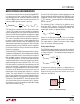
The LTC3859A includes current foldback for the buck
channels to help limit load current when the output is
shorted to ground. If the buck output falls below 70% of
its nominal output level, then the maximum sense volt-
age is progressively lowered from 100% to 40% of its
maximum selected value. Under short-circuit conditions
with very low duty cycles, the buck channel will begin
cycle skipping in order to limit the short-circuit current.
In this situation the bottom MOSFET will be dissipating
most of the power but less than in normal operation. The
short-circuit ripple current is determined by the minimum
on-time t
ON(MIN)
of the LTC3859A (≈95ns), the input volt-
age and inductor value:
DI
L(SC)
= t
ON(MIN)
(V
IN
/L)
The resulting average short-circuit current is:
I
SC
= 40% • I
LIM(MAX)
−
1
2
DI
L(SC)
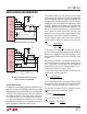
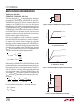
Fault Conditions: Buck Overvoltage Protection
(Crowbar)
The overvoltage crowbar is designed to blow a system
input fuse when the output voltage of the one of the buck
regulators rises much higher than nominal levels. The
crowbar causes huge currents to flow, that blow the fuse
to protect against a shorted top MOSFET if the short oc-
curs while the controller is operating.
A comparator monitors the buck output for overvoltage
conditions. The comparator detects faults greater than
10% above the nominal output voltage. When this condi-
tion is sensed, the top MOSFET of the buck controller is
turned off and the bottom MOSFET is turned on until the
overvoltage condition is cleared. The bottom MOSFET
remains on continuously for as long as the overvoltage
condition persists; if V
OUT
returns to a safe level, normal
operation automatically resumes.
A shorted top MOSFET for the buck channel will result in
a high current condition which will open the system fuse.
The switching regulator will regulate properly with a leaky
top MOSFET by altering the duty cycle to accommodate
the leakage.
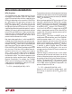
Fault Conditions: Over Temperature Protection
At higher temperatures, or in cases where the internal
power dissipation causes excessive self heating on chip
(such as INTV
CC
short to ground), the over temperature
shutdown circuitry will shut down the LTC3859A. When
the junction temperature exceeds approximately 170°C,
the over temperature circuitry disables the INTV
CC
LDO,
causing the INTV
CC
supply to collapse and effectively
shutting down the entire LTC3859A chip. Once the junc-
tion temperature drops back to approximately 155°C, the
INTV
CC
LDO turns back on. Long term overstress (T
J
>
125°C) should be avoided as it can degrade the perfor-
mance or shorten the life of the part.
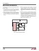
Phase-Locked Loop and Frequency Synchronization
The LTC3859A has an internal phase-locked loop (PLL)
comprised of a phase frequency detector, a lowpass filter,
and a voltage-controlled oscillator (VCO). This allows the
turn-on of the top MOSFET of controller 1 to be locked to
the rising edge of an external clock signal applied to the
PLLIN/MODE pin. The turn-on of controller 2’s top MOSFET
is thus 180 degrees out of phase with the external clock.
The phase detector is an edge sensitive digital type that
provides zero degrees phase shift between the external
and internal oscillators. This type of phase detector does
not exhibit false lock to harmonics of the external clock.
If the external clock frequency is greater than the internal
oscillator’s frequency, f
OSC
, then current is sourced continu-
ously from the phase detector output, pulling up the VCO
input. When the external clock frequency is less than f
OSC
,
current is sunk continuously, pulling down the VCO input.