
Datasheet


LTC3901
11
3901f
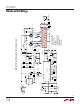
In the first period, MB turns off, E goes low (followed by
MA turning on), and the LTC3901 forces ME to turn off.
The primary side delivers power to the load through
MOSFET MF, T1 and L1.
In the second period, MA remains on, MD turns off, and
MC turns on. E goes high and the LTC3901 forces both ME
and MF to conduct. This is the free-wheeling period with
the T1 secondary output shorted.
In the third period, MA turns off, F goes low (followed by
MB turning on), and the LTC3901 forces MF to turn off.
The primary side delivers power to the load through
MOSFET ME, T1 and L2.
Like the second period, the last period is a free-wheeling
period. MB remains on, MC turns off, MD turns on, F goes
high, and the LTC3901 forces both ME and MF to conduct.
The timeout and current sense operations are the same as
in the push-pull application.
APPLICATIO S I FOR ATIO
WUUU
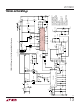
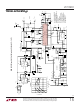
Figure 10. Simplified Isolated Full-Bridge Converter
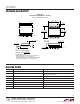
Figure 11. Full-Bridge Converter Switching Waveforms
LTC3722-1
FULL-BRIDGE CONTROLLER
OPTOCOUPLER
DRIVER
AB CD
COMP V
FB
FE
ISOLATION
BARRIER
T1
ME
MF
CSE
+
ME
CSE
–
CSF
+
MF
CSF
–
V
CC
GND
PV
CC
PGND
LTC3901
OUT
T2
COMP
V
OUT
V
IN
3901 F10
C
OUT
+
FB
SYNC
6
3
5
11
14
12
16
8,10
1
4,13
9
TIMER
MC
MD
MA
L2
L1
7
MB
T3
T4
the
SYNC
ME
MF
F
E
MD
MC
MB
MA
3901 F11
0V