
Datasheet


LTC4000
19
4000fb
For more information www.linear.com/LTC4000
Battery Instant-On and Ideal Diode External PMOS
Consideration
The instant-on voltage level is determined using the fol-
lowing formula:
V
OUT(INST _ ON)
=
R
OFB1
+R
OFB2
R
OFB2
• 0.974V
Note that R
OFB1
and R
OFB2
are the same resistors that
program the output voltage regulation level. Therefore,
the output voltage regulation level is always 122.5% of
the instant-on voltage level.
During instant-on operation, it is critical to consider the
charging PMOS power dissipation. When the battery volt-
age is below the low battery threshold (V
LOBAT
), the power
dissipation in the PMOS can be calculated as follows:
P
TRKL
= 0.86 • V
FLOAT
– V
BAT
[ ]
• I
CLIM(TRKL)
where I
CLIM(TRKL)
is the trickle charge current limit.
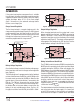
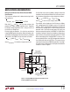
Figure 7. Charging PMOS Overtemperature Detection Circuit
Protecting PMOS from Overheating
applicaTions inForMaTion
On the other hand, when the battery voltage is above the
low battery threshold but still below the instant-on thresh-
old, the power dissipation can be calculated as follows:
P
INST _ON
= 0.86 • V
FLOAT
– V
BAT
[ ]
• I
CLIM
where I
CLIM
is the full scale charge current limit.
For example, when charging a 3-cell Lithium Ion battery
with a programmed full charged current of 1A, the float
voltage is 12.6V, the bad battery voltage level is 8.55V and
the instant-on voltage level is 10.8V. During instant-on
operation and in the trickle charge mode, the worst case
maximum power dissipation in the PMOS is 1.08W. When
the battery voltage is above the bad battery voltage level,
then the worst case maximum power dissipation is 2.25W.
When overheating of the charging PMOS is a concern, it is
recommended that the user add a temperature detection
circuit that pulls down on the NTC pin. This pauses charg-
ing whenever the external PMOS temperature is too high.
A sample circuit that performs this temperature detection
function is shown in Figure 7.
Li-Ion
BATTERY PACK
R
CS
M2
R
NTC1
TO SYSTEM
RISING
TEMPERATURE
THRESHOLD
SET AT 90°C
VISHAY CURVE 2
NTC RESISTOR
THERMALLY COUPLED
WITH CHARGING PMOS
VOLTAGE HYSTERESIS CAN
BE PROGRAMMED FOR
TEMPERATURE HYSTERESIS
86mV ≈ 10°C
CSN
BGATE
BAT
CSP
BIAS
NTC
LTC4000
162k
20k
R3
R4 = R
NTC2
AT 25°C
4000 F07
C
BIAS
R
NTC2
LTC1540
+
–
2N7002L