
Datasheet

LTC4011
19
4011fb
applicaTions inForMaTion
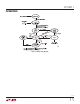
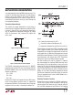
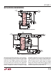
Figure 7. 3A NiMH Charger with Full PowerPath Control
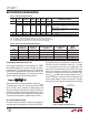
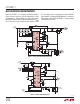
Figure 6. Minimum 1A LTC4011 Application
0.1µF
10µF
10µF
10µH
FAULT
INFET
CHRG
FROM
ADAPTER
12V
TOC
READY
0.033µF 0.068µF
20µF
0.1µF
4.7µH
20µF
FAULT
CHRG
TOC
READY
FROM
ADAPTER
12V
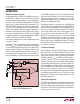
A full-featured 2A LTC4011 application is shown in Figure 8.
FET-based PowerPath allows for maximum input voltage
range from the DC adapter. The inherent voltage ratings
of the V
CELL
, V
CDIV
, SENSE and BAT pins allow charging
of one to sixteen series nickel cells in this application,
governed only by the V
CC
overhead limits previously dis-
cussed. The application includes all average cell voltage
and battery temperature sensing circuitry required for the
LTC4011 to utilize its full range of charge qualification,
safety monitoring and fast charge termination features.
LED D1 indicates valid DC input voltage and installed
battery, while LEDs D2 and D3 indicate charging. LED D4
indicates fault conditions. The grounded CHEM pin selects
the NiMH charge termination parameter set.