
Datasheet


LTC4020
13
4020fd
For more information www.linear.com/LTC4020
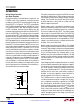
BG2 (Pin 33): V
OUT
side (step-up) primary switch FET
gate driver output.
INTVCC (Pin 34): Boosted Driver Refresh Supply. This
supply is regulated to 5V and is current limited to 150mA.
Connect a 2.2µF ceramic capacitor from this pin to PGND.
Boosted supply refresh diode anodes are connected to
this pin. Using this pin to power external 5V circuitry is
not recommended.
PGND (Pin 35): Switch high current return path for step-up
primary and step-down synchronous switches.
PVIN (Pin 36): High Current Input Supply Pin. Connect
10µF decoupling capacitor from this pin to PGND. The PV
IN
pin provides input supply current for the INTV
CC
internal
5V linear regulator.
BG1 (Pin 37): V
IN
side (step-down) synchronous switch
FET gate driver output.
SW1 (Pin 38): Switched node for step-down switches.
Connect the switched inductor to this pin. Connect the
primary switch FET source and synchronous switch FET
drain to this pin.
SGND (Pins 3, 29, Exposed Pad 39): Signal Ground Refer
-
ence. Connect to the output decoupling capacitor negative
terminal and battery negative terminal
. The exposed pad
(39) must be soldered to PCB ground (SGND) for electrical
connection and rated thermal performance.
pin FuncTions
Downloaded from Arrow.com.Downloaded from Arrow.com.Downloaded from Arrow.com.Downloaded from Arrow.com.Downloaded from Arrow.com.Downloaded from Arrow.com.Downloaded from Arrow.com.Downloaded from Arrow.com.Downloaded from Arrow.com.Downloaded from Arrow.com.Downloaded from Arrow.com.Downloaded from Arrow.com.Downloaded from Arrow.com.