
Datasheet


LTC4020
16
4020fd
For more information www.linear.com/LTC4020
operaTion
Functional Overview
The LTC4020 is an advanced high voltage power manager
and multi-chemistry battery charger designed to efficiently
transfer power from a variety of sources to a system power
supply rail and a battery.
The LTC4020 contains a step-up/step-down DC/DC
controller that allows operation with battery and system
voltages that are above, below, or equal to the input volt
-
age (
V
IN
). A precision threshold shutdown feature allows
incorporation of input voltage UVLO functionality using
a simple resistor divider. When in low current shutdown
mode, the IC input supply bias is reduced to only 27.5µA.
The LTC4020 charger is programmable to produce opti
-
mized charging profiles for a variety of battery chemistries.
The LTC
4020
can provide a constant-current/constant-
voltage charge characteristic with either C/10 or timed
termination for use with lithium based battery systems,
a constant-current characteristic with timed termination,
or an optimized 4-step, 3-stage lead-acid charge profile.
Maximum battery charge current is programmable using
a sense resistor, and a charge current range adjust pin
allows dynamic adjustment of maximum charge current. A
switcher core current limit adjust pin also allows dynamic
limiting of power available to the system by virtue of limit
-
ing maximum current in the DC/DC converter inductor.
The LTC
4020
preconditions heavily discharged batteries
by reducing charge current to one-fifteenth of the pro
-
grammed maximum. Once the battery voltage climbs above
an internally set threshold, the IC automatically increases
maximum charging current to the full programmed value. A
bad battery detection function signals a fault and suspends
charging should a battery not respond to preconditioning.
Battery temperature is monitored using a thermistor
measurement system. This feature monitors battery
temperature during the charging cycle, suspending the
charge cycle and signaling a fault condition if the battery
temperature moves outside a safe charging range of 0°C
to 40°C. The charge cycle automatically resumes when
the temperature returns to that safe charging range.
Instant-on PowerPath architecture ensures that an applica
-
tion is powered immediately after an external voltage is
applied,
even with a completely dead battery, by prioritiz-
ing power to the application. Since the controller output
(
V
OUT
) and the battery (BAT) are sometimes decoupled,
the LTC4020 includes an ideal diode controller, which
guarantees that ample power is always available to V
OUT
if there is insufficient power available from the DC/DC
converter. Should there be no input power available (V
IN
),
the LTC4020 makes a low impedance connection from the
battery to V
OUT
though the PowerPath FET. Battery life
is maximized during periods of input supply disconnect
by reducing the LTC4020 battery standby current to less
than 10µA.
The LTC4020 contains two digital open-collector outputs
that provide charger status and signal fault conditions.
These binary coded pins signal battery charging, standby
or shutdown modes, battery temperature faults, and bad
battery faults.
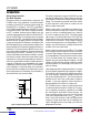
DC/DC Converter Operation
(See Block Diagrams)
The LTC4020
uses a proprietary average current mode
DC/DC converter architecture.
As shown in Figure 1, when V
IN
is higher than V
OUT
dur-
ing step-down (buck) operation, switches A (driven by
pin TG1)
and B (driven by pin BG1) perform the PWM
required for accommodating power conversion. Ideally,
switch D (driven by pin TG2) would conduct continuously
and switch C (driven by pin BG2) would stay off, making
PWM switching action much like that in a synchronous buck
topology. Switch D uses a bootstrapped driver, however,
so switch C conducts for a minimum on time of 150nS
each cycle to refresh the driver and switch D is disabled
to accommodate this refresh time. A 75ns non-overlap
period, separates the conduction of the two switches,
preventing shoot-through currents.
When V
IN
is lower than V
OUT
during step-up (boost) op-
eration, switches C and D perform the PWM required for
accommodating power conversion. Ideally
, switch A would
conduct continuously and switch B would stay off, making
Downloaded from Arrow.com.Downloaded from Arrow.com.Downloaded from Arrow.com.Downloaded from Arrow.com.Downloaded from Arrow.com.Downloaded from Arrow.com.Downloaded from Arrow.com.Downloaded from Arrow.com.Downloaded from Arrow.com.Downloaded from Arrow.com.Downloaded from Arrow.com.Downloaded from Arrow.com.Downloaded from Arrow.com.Downloaded from Arrow.com.Downloaded from Arrow.com.Downloaded from Arrow.com.